Friday, December 23, 2011

Lexmark T Series -- Printhead Service Aid

Any time you need to work on a printhead with the toner cartridge access door's cover off, and the door unlatchable, put a bungee cord across the door to hold it closed, like so.

Way better.

# # #


# # #

Thursday, December 22, 2011

Oki 320/1 Turbo -- Ribbon Drive Gear Case

An Okidata 320 Turbo came in with an inoperative ribbon drive. That's a rare failure -- the ribbon drive seldom gives trouble on these machines. The usual fix is to replace the gear case, P/N 51238801.

Replacing the gear case is not difficult, but there's a little booby-trap to be avoided. The following procedure begins with the space motor assembly already off the carriage frame, but still attached to the flat cable. Proceed as follows:

1) Flat Cable
- Unplug it and unhook the gear case claw at the right rear corner. Nudge the corner of the gear case upward a bit and the cable can be slid away. Here's a view of the cable part way off.

2) Gear Case
- There are four claws altogether that secure the gear case to the space motor frame. Unhook the claws and the gear case can be lifted off the motor, but be careful; this is where the booby-trap enters into it.

The upper and lower halves of the gear case shell are lightly snap-fitted together. They separate easily. Careless removal of the gear case can result in a spill of its tiny components.

Here's a view of the gear case's interior.

The small gear that shuttles back and forth to maintain unidirectional output has lost two teeth. The only reason I can think of for that to happen is that a ribbon cartridge may have seized while operating.

Anyway, this is from a relatively new printer, so I'm going to just replace that one damaged gear with one from a salvaged gear case. The rest of it is in fine condition, well lubricated with grease that's still fresh and effective.

- - -

That worked fine.

Always check printhead/platen gap after any carriage work on these printers. You might think you haven't done anything to disturb the adjustment, but it never seems to be correct after removing and reinstalling a space motor. The gap figure is 0.016" with the forms thickness lever all the way toward the platen.

- - -

Gear Case Operation

a) Forms Thickness Adjustment

The blue sector gear with the handle, along with the two gears down in front, act on the forms thickness adjustment screw (not seen in the photo). Moving the handle toward the front of the printer rotates the screw CW, increasing the printhead/platen gap.

The sector gear's handle has five detented positions, with position '1' being the single sheet setting (nearest the platen). Each detent-to-detent increment of sector gear rotation toward positon '5' turns the gap adjustment screw approximately 76 degrees CW, increasing the gap by 0.00275". The full range of sector gear rotation from position '1' through to position '5' increases the gap by 0.011". A gap that's been correctly adjusted for 0.016" at position '1' will become 0.027" at position '5'.[1]

b) Forms Thickness Setting Sensing

Note the two leaf-spring contacts in front of the blue lever. Their lower ends protrude beneath the gear case, where they're poised above contact pads on the space motor PCA. As the forms thickness setting is increased, those contacts make/break to inform the controller of the setting. There's a third, common contact between those two contacts that's always made.

The outboard (leftmost) contact is designated 'SW1'; the inboard contact is designated 'SW2'. Following are the switch states for the five thickness settings: (C=closed; O=open)

1. Both open.

2. SW1-C; SW2-O.

3. Both closed.

4. Both closed.

5. SW1-O; SW2-C.

The controller uses the thickness setting information from SW1 and SW2 to adjust print speed and needle energy according to forms thickness. At thickness setting '5', print speed is perceptibly reduced; needle energy is maximized.

c) Ribbon Drive

The gear near the top centre in the photograph is the ribbon drive's input gear. It's driven directly from the space motor's upper shaft end, so it's always reversing direction.

The ribbon drive's output gear/spindle must always turn CW. The small shuttle gear is what gives the ribbon drive it's constant CW output, regardless of input direction.

CCW input rotation forces the shuttle gear to travel up its slot and engage the single idler between it and the output gear -- CW output rotation results.

CW input rotation forces the shuttle gear to travel down its slot and engage the two-idler series -- CW output rotation results.

Maintenance

The ribbon drive is reliable and mostly trouble-free. Gear tooth breakage incidents like the one described earlier above are uncommon.

With age, the grease installed at the factory will eventually turn to sludge. If the shuttle gear's action is impaired by sludgy grease, ribbon drive can become erratic. A shot of WD-40 may clear it up in a pinch. It's not difficult to dismantle the gear case, clean all the components with Varsol and reassemble it with fresh grease suitable for fine mechanisms.

- - -

Note:

[1] The dimensions given are not absolute; they're very close approximations.

# # #


# # #

Lexmark T64X -- Fuser Resistances & Pin Assignments

Resistance Values

Lamp Circuit: Approx. 1.5 ohms.

Thermistor: Approx. 350 kohms at room temperature.

- - -

Cable Connection J1

1. NARMEDIA*[1]

2. Thermistor Return -- J5-1

3. Thermistor -- J5-2

4. GND[2]

5. THUMP -- J4-2

6. +5V

7. THUMPRET -- J4-1

8. EXIT SNS*[1]

9. +3.3V[3]

10. CLK[3]

11. DATA[3]
- - -

Notes:

[1] Paper present = LO; Paper not present = HI.

[2] Lexmark's practice is to tie DC (logic) ground to chassis ground. You can always use chassis ground for a ground reference on Lexmark's machines.

[3] The T64X fuser PCA has a serial EEPROM mounted on its underside. It's an Atmel 24C02BN -- a 2k (256x8) unit. I can find no information regarding why it's there or what it does.

# # #


# # #

Wednesday, December 21, 2011

Lexmark T63X -- Touchy Cover Interlock

If a machine has a touchy cover interlock giving false 'Close Door or Insert Cartridge Messages', don't try bending the switch's actuating lever to 'adjust' it -- that's asking for trouble. Instead, 'bulk up' the switch's lever with 1/8" diameter heat-shrink tubing. Three 5/16" lengths of Alpha FIT-221 tubing are ideal. It should look like this when you're done installing the tubing lengths.

The third tubing length can just barely be gotten slipped on. Make sure you've fully shrunk the first two tubing lengths, and the third length will go on.

# # #


# # #

Lexmark T63X -- Fuser Resistances & Pin Assignments

Resistance Values

Lamp Circuit: Approx. 1.5 ohms.

Thermistor: Approx 465 kohms at room temperature.

- - -

Cable Connection J1

1. NARMEDIA*[1]

2. Thermistor Return -- J6-1

3. Thermistor -- J6-2

4. GND[2]

5. THUMP -- J4-2

6. +5V

7. THUMPRET -- J4-1

8. EXIT SNS*[1]

- - -

Notes:

[1] Paper present = LO; Paper not present = HI.

[2] Lexmark's practice is to tie DC (logic) ground to chassis ground. You can always use chassis ground for a ground reference on Lexmark's machines.

# # #


# # #

HP LaserJet P2055dn -- Fuser Resistance Checks

Heater: Approx. 16 ohms.

Thermistor: Approx. 424 kohms at room temperature.

# # #


# # #

Tuesday, December 20, 2011

HP LaserJet P2055dn -- Fuser Replacement

Fuser P/N is RM1-6405. The removal procedure for this fuser is a bit more intricate than for most fusers, but it's quite straightforward. Proceed as follows:

1) Cartridge

2) Tray 2

3) Left Side Cover
- Front door open.
- Pry at front lip and at centre of top lip to free the cover.
- NOTE: The small claw at the centre of the top lip is liable to break. No real harm is done by that.

4) Right Side Cover
- Open the upper back door (green handle).
- Pry at top and bottom of rear lip.
- Pry at top lip near 'Ready' indicator.

5) Rear Cover w/Duplexer Platform
- Lower the duplexer platform (press on the green tab to the left of the Tray 2 pickup roller).
- Close the upper back door.
- Open the lower back door.
- Five M3x8mm washerhead screws.
- One small claw at the extreme lower right.
- Slide the assembly out the back.

6) Reverse Sensor Assembly (The prominent sensor at the rear.)
- One M4x10mm bright pan head threading screw.
- One three-conductor cable connection.

7) 'In-The-Way' Cabling
- The cabling that runs under the reverse sensor has nothing to do with the fuser's connections, but it must be freed and moved aside.
- Six cable connections. 'Best to disconnect them in sequence from your right to your left. Reconnect them in the reverse sequence.

8) Media Feed Guide
- One M3x6mm black washerhead screw at centre.
- Slide the item to your right to free it.
- NOTE how the item hooks a two-conductor blue cable.

9) Fuser Cabling
- One red/blue/green fuser exit sensor cable.
- One two-conductor blue thermistor cable.
- One white wire at the extreme left.
- One two-conductor power connector at the extreme right. (Press its latch tab forward.)

10) Three Gears
- NOTE: The front door must be closed for this step.
- At the right side, there are three gears accessible for removal.
- Frontmost, largest gear -- one claw.
- Upper, smallest gear -- one claw.
- Rearmost gear with 'handle' -- one claw. You may have to nudge it CW a bit to get it out. NOTE that there's a timing relationship associated with this gear. The flange on its inboard end is notched to preclude getting it back in place out-of-time with the sector gear below it. A protrusion on the top of the gear aligns with a notch in the gear above it.

11) Fuser
- Three[1] M3x8mm washerhead screws.
- NOTE that the two lower screw holes are for the rear cover.
- Slide the fuser out the back.

- - -

Note:

[1] The new OEM replacement fuser had holes for only two upper fastening screws. The hole for the third fuser fastening screw had been deleted.

# # #


# # #

Monday, December 19, 2011

HP LaserJet 4100 -- 500-Sheet Add-On Tray C8055A

Routine Teardown/Overhaul

Proceed as follows:

1) Tray
- Replace separation roller P/N RF5-3114 A/R.

2) Rear End Cover
- Spread the sides at the bottom a little to free two claws. Tip it up and off.

3) Upper Left Side Rail
- Two M4x10mm YZD pan head threading screws.

4) Upper Right Side Rail
- Two M4x10mm YZD pan head threading screws.

5) Top Outfeed Roller
- One e-clip at right side bearing.
- Remove gear and bearings and clean them w/Varsol.
- Clean the roller w/lacquer thinner.
- Clean pinch rollers A/R w/methyl hydrate.
- At reinstallation, apply light mineral oil sparingly to the bearings.

6) Top Cover
- Six M4x10mm YZD pan head threading screws. At reinstallation, NOTE that the four M4 screw holes nearest the corners are for the upper rails' screws.
- Two M3x6mm black pan head screws in front of and behind the exposed gears.
- One M3x6mm black pan head threading screw inboard of the exposed gears.
- CAUTION. As you lift away this cover, make sure that the pickup assembly doesn't come up with it -- that can get messy.
- Note the spring-loaded clutch lever by the upper right corner of the tray opening. Remove the lever and spring. Here's how they look when correctly in place awaiting top cover reinstallation.

7) Pickup Assembly
- One two-conductor cable connection.
- Free the cable from its restraints.
- Lift out the assembly.
- EXAMINE the pickup solenoid for any tendency for its flapper to stick in the energized position. If in doubt, remove the solenoid -- it's much easier to check this with the solenoid out of the assembly. See this post.
- Replace feed roller P/N RF5-3114 A/R.
- Replace pickup rollers P/N RB1-8957 A/R. (The pickup rollers are extremely long-lasting and reliable; they seldom need to be replaced.)

8) PCA Cover
- Two claws at the top edge.

9) PCA P/N RG5-5539
- Three cable connections.
- One M4x10mm YZD pan head threading screw.
- Apply WD-40 to the pushbutton switches and actuate them many times. Blow them out w/compressed air.

10) Reassemble.

# # #


# # #

Sticky Solenoids

Pictured below is a pickup solenoid from a LaserJet 4100's Tray 2. It's in its normal, de-energized state.

And here it is stuck in its energized state, in the absence of any applied energy.

On the solenoid's frame, there's a tiny rectangle of foam rubber adhered with pressure-sensitive adhesive; it's there to quiet the solenoid's operation. The foam rubber deteriorates with age, and the adhesive bleeds through. The result is a sticky solenoid that will cause the clutch it's controlling to double-cycle. That can result in some quite mystifying symptoms. Here's a view of the ruined foam rubber.

HP doesn't break out this solenoid as a service replacement part, but it's not at all difficult to get a sticky solenoid working properly.

First, you have to remove all traces of the adhesive with lacquer thinner. (The adhesive is tenacious stuff, but it does come off. Be sure to get rid of all traces of it.) Wrap four thicknesses of electrical tape around the flapper and reassemble the solenoid.

The solenoid will work fine, but it won't be as quiet as it was. It will make an audible, though not objectionable, muffled 'click' every time it's energized.

This style of solenoid is widely used to control clutches, and they can all get sticky with age. The symptom this one produced in a 4100 was rather odd.

On a multi-page print run, every third page would be a blank sheet. No error would be reported, but the printer would stop printing, and just keep running doing nothing. Opening and closing the lid would cause printing to resume for two pages, then the same blank sheet incident would occur.

Looking in the back of Tray 2, I could see that the pickup rollers were double-cycling. 'Explained a lot.

The double-cycling didn't affect the first page's timing, of course, and it didn't affect the second page either. But it always caused the third sheet to enter the printer too early. Whenever a sheet is fed too early, a misprint (blank sheet) ensues. The curious thing is that there was no error displayed. Misprints are supposed to give '41' errors. It looks to me like the 4100 has a bug in its firmware, such that it can't interpret the particular condition I was seeing. It just gets bewildered, and goes into a 'do nothing useful' loop.

Any solenoid that sticks long enough to cause double-cycling of a clutch will cause trouble of some sort. Any time you have access to a solenoid of this type, take a minute to press its flapper closed and see that it doesn't stick.

When you encounter a sticky solenoid in a machine, and the machine has other, similar solenoids in it, examine them all. The odds are good that they'll be sticky as well. The printer this solenoid was in had a Tray 1 solenoid that was even worse for stickiness. I think there might be some environmental factor that contributes to the foam rubber's deterioration.

# # #


# # #

Saturday, December 17, 2011

HP LaserJet 42X0/43X0 -- Swing Plate Assembly Characteristics

Functionality

Here's a view of a service replacement swing plate assembly.

The assembly resides on the inboard side of the right side vertical chassis member, where it transmits rotation from the main drivetrain to the fuser when the toner cartridge access door is closed.

Its gears are in constant mesh with the main drivetrain, but opening the toner cartridge access door causes the black gear at its rear to disengage from the fuser to facilitate clearing a paper jam. The spring-loaded lever at the upper right is actuated when the toner cartridge access door is closed -- that's what forces the black gear to engage with the fuser's drive gear.

Maintenance/Failure Mechanisms

The two gears lead a hard life, and are prone to wear badly leading to noisy operation. Unit replacement is the only solution. See this post for the procedure.

There is a shortcut repair method of replacing only the black gear at the rear. That method is pretty much worthless, and is strongly advised against. The two gears tend to wear about equally; replacing only one is not a legitimate repair method.

The fit of the fuser in the 42X0/43X0 machines probably contributes to the wear of the swing plate assembly's two gears. The clip-fastened fuser has a sloppy fit in the chassis that can't be conducive to establishing correct gear mesh -- it's a design flaw that will never be corrected.

Part Numbers

A complete, OEM swing plate assembly is P/N RM1-0043-060. When ordering from a vendor, specify that you want the complete OEM unit. Some outfits apply almost the same P/N to the black gear alone.

# # #


# # #

Friday, December 16, 2011

HP LaserJet 4100 -- Paper Feed Assembly Characteristics

[NOTE: The following applies equally as well to the LaserJet 40X0.]

- - -

Functionality

Here's a view of the right side end of the assembly.

The white gear is in constant mesh with the printer's drivetrain, and is the clutch-controlled input to the feed shaft and the black gear.

With the clutch de-energized, the white gear freewheels to no effect.

With the clutch energized, the white gear is coupled to the feed shaft and to the black gear. The feed shaft can transport paper, and the black gear can supply input rotation to Tray 2's pickup assembly through a large tandem idler that's behind it. The black gear's hub is a one-way roller-bearing clutch; if counter-rotated, the black gear will freewheel.

The paper feed assembly only deals with paper from Trays 2 and 3. When printing from Tray 1, the paper feed assembly is bypassed entirely.

Maintenance/Failure Mechanisms

There's only one bronze bearing that might be prone to accumulate sludge. Remove the pinch-pressure spring and one e-clip, and the bearing can be removed for cleaning.

See this post regarding swollen rubber rollers.

The electromagnetic wrap-spring clutch is rugged and reliable, but it has a big job to do, especially on machines with an add-on tray. The clutch supplies rotation to the feed roller, Tray 2's pickup assembly and Tray 3's pickup assembly. Any hesitancy or slippage in the clutch will result in mysterious, random paper jam incidents. As mentioned earlier, printing from Tray 1 bypasses the paper feed assembly entirely, so that can be helpful for troubleshooting.

Any slippage of the black gear's one-way roller bearing clutch will retard Tray 2 and Tray 3 pickup assembly operation, also resulting in mysterious, random paper jam incidents.

Outright replacement of the assembly is the quick solution, but the units seldom, if ever, fail outright. They become flaky with age due to contaminants in the clutches.

The black gear's clutch can be flushed with Varsol in a parts washer tank, and blown dry with compressed air. The shaft it rides on must be immaculately clean. On reinstallation, lubricate the clutch with WD-40.

The electromagnetic clutch can be dismantled and cleaned. Its components must all be perfectly free of dust or lubricant of any kind.

Part Numbers

A LaserJet 4100 paper feed assembly is P/N RG5-5086.

A LaserJet 40X0 paper feed assembly is P/N RG5-2651.

They look interchangeable to me, but I haven't tried it to confirm whether they are or not.

No service replacement components are available for either one.

# # #


# # #

HP LaserJet 40X0 -- Registration Assembly Characteristics

[NOTE: The following applies equally as well to the 4100.]

- - -

Functionality

The registration assembly in the LaserJet 40X0 is misnamed, actually. The 'registration' roller is in constant mesh with the drivetrain, and has no control whatsoever over leading edge registration timing. The registration assembly is strictly a constant-mesh paper conveyor.

There's a lightly spring-loaded 'gate' that rides on the upper roller, and presents four 'barriers' to the leading edge of a sheet of paper just before it enters the rollers' pinch. The gate is there to correct skew. By colliding with the straight row of barriers prior to getting pinched by the rollers, a sheet's leading edge will enter the rollers' pinch in alignment with the rollers.

Maintenance/Failure Mechanisms

See this post regarding bronze sleeve bearing maintenance.

See this post regarding swollen rubber rollers.

Loose Rollers

Further to the rubber rollers, the rollers can lose their grip on their steel shaft, rendering them ineffectual. The two outermost rollers seem to be the most prone to that.

Pictured below are a good new assembly, and an old defective one with two loose rollers. Note that I was able to shove the loose rollers way over out of place.

Those two outermost rollers are completely free-turning on their shaft. Unless they're out of place like the one's pictured, visual inspection won't reveal the condition. You have to take the assembly out of the machine.

With the registration assembly out, fold back the spring-loaded flap to get the pinch rollers away from the rubber rollers; then it's easy to check whether any rubber rollers are loose.

The defect pictured was causing mysterious, crumply jams at the registration roller, when all appeared to be in order.

Registration Gate Barrier Wear

In the following photograph, a new registration assembly is perched on top of an old, worn one.

Note the registration gate barriers. The new barriers have square-cornered ends. The old barriers are worn away to an angle. That amount of wear would render the skew-correction function inoperative.

Part Numbers

A LaserJet 40X0 Registration Assembly is P/N is RG5-2652. There are no service replacement components available for the assembly.

The registration assembly for the LaserJet 4100 is very similar but not identical. Its P/N is RG5-5085. No service replacement components are available for it either.

The photograph below shows a distinguishing feature.

Above is the 40X0 part. Below is the 4100 part. Note the cut/punched raised portion of the flap near the left side end of the 4100 part. That provides clearance for a sensor toggle that's not present in the 40X0.

# # #


# # #

Thursday, December 15, 2011

Fujitsu DL6400 -- Jam Lever Alarm

The subject alarm can be falsely caused by a flaky sensing switch. Here's an explanation of the alarm, and the jam lever's operation.

- - -

The DL6400's front tractor has a curious feature associated with it -- the tractor and the pinch roller set directly above it can be unlatched from their normal operating position, and opened up somewhat to facilitate clearing a jam. There's a green tab and a lower black tab at either side of the front tractor cavity. You press the green tabs down to open the mechanism; press the black tabs up to close and latch it. Here's a view of that in its normal operating position.

And here it is opened up for clearing a jam. (The difference is subtle -- the position of the green lever is the key to seeing it.)

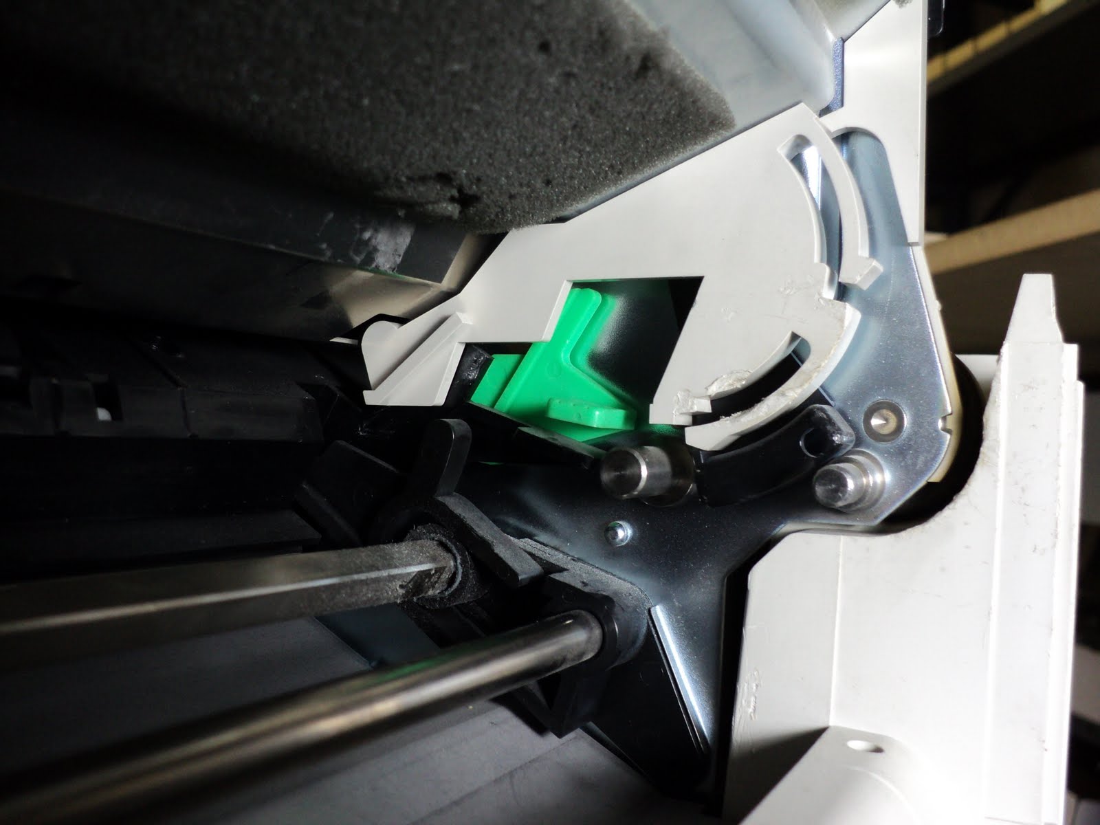
The paper path above the tractor is opened up slightly, the tractors are lowered and disengaged from the drive train, and a switch at the left side of the chassis (the 'OC switch unit') has been opened. The switch is the sensor for open/closed status of the front tractor.

The printer's controller considers the open state to be a fatal error condition, and displays a "Jam Lever Alarm" indication if you unlatch the tractor while powered on, or if you power on with the tractor unlatched. The alarm looks like this.

'PAPER OUT' is flashing, 'COUR 10' and 'Time PS' are lit. (The 'MENU 1' LED has no relevance to this.) The printer is inoperative. To recover from the alarm, latch the tractor back in its normal operating position and power off and back on.

The sensing switch, the 'OC switch unit', is on the left side vertical chassis member. Prop the chassis up in its service access position to get at the switch. Here's a view of the switch.

Note the disengaged gear that's below and to the right of the switch; that's the tractor drive gear. It's normally in mesh with the gear above it when the tractor is latched up in place.

And here's the switch free of the chassis. (Just pinch its claws to remove it.)

A switch that develops high contact resistance with age will give false Jam Lever Alarms. A service replacement switch is P/N CA02464-F365. The switch's two-conductor cable plugs into connector 'CNMUOC' on the Connector PCA.

WD-40 is sometimes helpful for a flaky switch. Apply it around the switch's plunger and work the plunger many times. Check the switch's closed resistance with an ohmmeter; it might be restored to normal.

In a pinch, you could cut the switch's cable and short the wire ends together to get a printer going.

# # #


# # #

Wednesday, December 14, 2011

Fujitsu DL6400 -- Cover Interlocks

There are two cover interlocks -- a safety interlock that disables carriage drive,[1] and a logical interlock that informs the controller of a cover open condition.

- - -

The safety interlock switch resides at the upper right front corner of the chassis. Here's a view of it.

The switch is actuated indirectly by means of a pivoted paddle that's quite strongly spring loaded. 'Easiest way to cheat it is to clamp a small set of Vise-Grips on the upper corner of the switch's mounting bracket, just above the actuating paddle, like so.

Clamp on the Vise-Grips good and tight so they won't tumble on you while the machine is running.

- - -

The logical interlock comprises two Hall-effect sensors at the upper edge of the control panel. They're 'actuated' by a permanent magnet embedded in the front of the access cover.

Cheating those sensors is a bit awkward; here's the best arrangement I've come up with for doing it so far.

Lash a suitable magnet in place with rubber bands. (The magnet in the photo is from a cabinet door latch.) The sensors are sensitive to magnetic polarity, so you have to experiment a bit to find the magnet orientation that works.

- - -

Note:

[1] An inoperative safety interlock will cause a Left End Alarm condition. See this post for an explanation.

# # #


# # #

Lexmark T65X -- Fuser Teardown/Overhaul Checklist

This document is a condensation of a procedure. It can serve as a checklist once one is familiar with all the information in the procedure.

- - -

Proceed as follows:

1) Lower Rear Cover

2) Lamp

3) Thermistor Cable

4) Top Cover

5) Stripper Bar Torsion Springs

6) Exit Roller

7) Idler Gear

8) Pressure Roller Springs
- Unhook them at the lower front of the frame.

9) Ring Gear

10) Left Side Bearing

11) Hot Roller w/Bushings

12) Right Side Bearing

13) Input Ramp

14) Stripper Bar

15) Pressure Roller w/Bearings

- - -

At this point, you can proceed in either of two ways.

a) Carry on with the full procedure for a thorough overhaul.

b) Abbreviate the procedure for a 'good-enough' overhaul.
- Apply a couple of drops of light mineral oil to the pressure roller arms' pivot points.
- Examine the sensor toggles.
- Reassemble w/new parts A/R.

- - -

16) Output Ramp

17) Pressure Roller Springs

18) Right Side Pressure Roller Arm

19) Left Side Pressure Roller Arm and Link

20) PCA

21) Solenoid

22) Main Connector

23) Right Side Ground Continuity Tab Contact

24) Static Brush and Left Side Ground Continuity Tab Contact

25) Right Side Wiring Guide

26) Frame Latches w/Springs -- Left and Right Side

26) Reassemble w/new parts A/R

- - -

Frequently Replaced Parts

Assembly, 115V Fuser, T65X Type 1: P/N 40X4418

Assembly, 115V Fuser, T65X Type 2: P/N 40X5854

Bearing, Hot Roll [6003Z: 17mm bore x 35mm O.D. x 10mm thick]: P/N 99A0143

Bearing, Pressure Roller [R3Z: 0.1875" bore x 0.500" O.D. x 0.196" thick]: P/N 99A1621

Pressure Roller, 28mm dia: P/N LPR-T650

Coated (Hot) Roller, 30mm dia: P/N UFR-T650

# # #


# # #

Monday, December 12, 2011

IBM 4232-302 -- Paper Entry Chute

Ordinarily, one would never have to do anything with this item, but a printer came in that had an EOF sensor fastening screw seized in its threaded insert and broken off. 'Easiest fix was to swap out the chute for one from a parts machine.

The chute is held in place by six claws on its underside -- they're visible from underneath. The things are old and brittle, so the claws are easily snapped off. If a chute has at least four claws intact, it will stay in place fine. If it came to it, it wouldn't be difficult to fasten a chute with flathead screws.

The carriage cable is secured to the chute's upper surface by two black plastic clips. Those are removed by squeezing their rear projections with pliers and pushing them through their rectangular holes; it takes quite a squeeze and push to persuade them to leave.

Here's a view of the broken screw seized in its insert, along with one of the cable clips I just mentioned.

# # #


# # #

IBM 4232-302 -- Main Sensor Cable Removal

This procedure deals with the cable that connects to the Logic PCA at J3 (upper right corner of the PCA). It's the cable for the AFTA sensor, the EOF sensor, the Door Closed sensor and the carriage motor.)

Proceed as follows:

1) Cover off.

2) Forms Device
- Remove it.

3) Left Side Air Deflector
- It slips off the frame rearward and upward. There's a rightward-projecting pin on it that the rear shield interferes with a bit.

4) Right Side Air Deflector
- One M4x10mm slotted hex washerhead screw (6mm A/F hex).
- Free the control panel cable from its clip at the right side.
- Lift the deflector off the frame while flexing the rear shield A/R.

5) Rear Shield
- At left side, two M4.5x10mm hex washerhead threading screws(7mm A/F hex).
- At right side, one M5x8mm hex washerhead screw (8mm A/F hex). Just back it out till it's clear of the rear shield.
- Lift the rear shield out.

6) Cable
- CAUTION: The cable connector at an elderly EOF sensor is likely to be fragile and stubborn. Disconnect it with great care.
- Disconnect at carriage motor, DC sensor, AFTA sensor and EOF sensor
- The cable is easily extracted from the two leftward cable restraints. The cable restraint by Logic PCA J7 has to be dislodged from underneath.
- Free the cable from the chassis entirely.

# # #


# # #

IBM 4232-302 -- Power Supply Removal

Proceed as follows:

1) Cover off.

2) Forms Device
- Remove it.

3) Left Side Air Deflector
- It slips off the frame rearward and upward. There's a rightward-projecting pin on it that the rear shield interferes with a bit.

4) Right Side Air Deflector
- One M4x10mm slotted hex washerhead screw (6mm A/F hex).
- Free the control panel cable from its clip at the right side.
- Lift the deflector off the frame while flexing the rear shield A/R.

5) Rear Shield
- At left side, two M4.5x10mm hex washerhead threading screws(7mm A/F hex).
- At right side, one M5x8mm hex washerhead screw (8mm A/F hex). Just back it out till it's clear of the rear shield.
- Lift the rear shield out.

6) Ground Braid
- One M4x10mm pan head screw w/captive flat washer.

7) Green Ground Wire at Left Side
- One M4x10mm hex washerhead screw (7mm A/F hex) at left side vertical chassis member.

8) Power Supply
- Cable connection at J6.
- Three M4.5x16mm hex washerhead threading screws.

# # #


# # #

Sunday, December 11, 2011

Lexmark T65X -- Burnt Fuser Lamp Terminal

I pulled the fuser out of a functioning T650 the other day, and was greeted by a very nasty looking left side end lamp terminal. I propped up the end of the fuser on a rigid surface so I could really bear down with a screwdriver, and the screw broke off, like so.

I imagine what happened here is that the screw had been installed only finger tight, and the resulting electrical connection was good enough to work, but resistive enough that it heated up something fierce. Eventually, it got hot enough that it effectively spot-welded itself together and continued to work. I had to peel the lamp's terminal off with a knife blade.

This sort of thing is usually repairable. The key to it is getting the seized screw end drilled through, and the key to that is getting a good, dead-centre centre punch impression in the screw. Easier said than done, but I got lucky.

A 7/64" drill in the drill press took care of the screw remnant, and left me with a hole just a little undersize for an M3 screw. I ran an M3 threading tap through it to create a vestigal thread, and rounded up the bits I'd need to refasten the terminal. Here's a view of the repair almost done.

The terminal's been well scraped. A small diameter sanding drum in a hand grinder took care of the bubbled, bloated plastic by the terminal.

The screw is 14 mm long; I cut down a longer screw to obtain that length. (The screw must be no longer than necessary so it won't interfere with inserting the fuser in the printer.)

And after a good scraping of the lamp's terminal, it was all ready to go back together, like so.

That'll work fine.

If I were doing this again, I'd drill a clearance-diameter hole for the screw and not bother with threading an undersize hole. There's really nothing gained by doing that.

In any event, the lesson is to be certain that lamp terminal screws are good and snug. Those lamps draw a lot of current, and they need good, low-resistance connections to draw it through.

# # #


# # #

Friday, December 9, 2011

IBM 4232-302 -- EOF Sensor

The EOF (End of Forms) sensor resides at the lower left of the front door opening. It's fastened by two M3x16mm slotted hex head screws w/captive flat washers (4mm A/F hex). Here's a view of it.

The unit is actually two sensors -- an EOF sensor and a 'hole count' sensor.

The EOF sensor is toward the right side of the unit. It 'watches' for passage of a form's trailing edge, and signals the Logic PCA accordingly so that printing is halted 6.3" later.

The hole count sensor is toward the left side of the unit. It monitors the passage of tractor pin holes as paper is fed. If no hole passages are observed in the course of 2" of commanded paper feed, the printer halts and displays a "PAPER JAM" message.

The sensor's lateral position is adjustable, so the hole count sensor can be perfectly aligned with the holes in mounted forms. There's a little nub on the upper ledge of the sensor's body that indicates the sensor's physical position within. In the photograph, the sensor is slightly off to the right. Perfect alignment of the sensor with forms' holes will preclude false paper jam messages.

The Sensor Test in the Offline CE Tests displays the state of both sensors. For what it's worth, here are the pin assignments of the sensor's cable connection:

Pin 1: EOF sensor output. LO = paper in; HI = paper out.

Pin 2: Ground.

Pin 3: Hole count sensor output. LO = paper. HI = hole.

Pin 4: VCC (+5V).

- - -

Early EOF Sensor

There's a black-coloured EOF sensor that I take to be an early version. It has a nub on it for sighting the lateral position adjustment, just as the blue-coloured version has, but it's very different internally. Here's a view of the underside of one.

Yikes! Four adjustment pots. That looks to me like a very good thing to stay away from.

The blue version has had the adjustability engineered out of it, and is probably much more reliable as a result.

Should you need to disconnect one of these, watch out. The tiny cable connector is stubborn and very easily damaged. Pry it out gently with a jeweller's screwdriver.

# # #


# # #

IBM 4232-302 -- Paper Present Sensor

The Paper Present (PP) sensor rides on the right side of the carriage facing the paper path. Here's a view of it in a machine with an F2 (push tractor) forms device.

It's a reflective object sensor (ROS) that 'sees' the leading edge of the forms arrive as they're loading, and informs the Logic PCA so the paper can be positioned accordingly.

No useful information about the sensor's 'health' can be obtained by a voltmeter. The Sensor Test in the Offline CE[1] Tests displays the sensor's state.

A 'blind' sensor will let loading paper go by much too far, then the machine will stop and display "012 CHECK PAPER PATH".

- - -

Note:

[1] 'CE' is short for 'Customer Engineer' -- a bit of IBM newspeak meaning 'technician'. Think about it. What the bleep should 'customer engineer' properly mean? -- 'one who designs/constructs customers', surely. 'Customer engineer' is the sort of Orwellian language abuse that corporations deserve to be put to death for.

# # #


# # #

IBM 4232-302 -- Cover Interlocks

There are two cover interlocks, one for the top access cover and one for the front door. They're both Hall-effect sensors 'actuated' by permanent magnets.

The top access cover's magnet is situated where it can act on a sensor that's inside the rear left corner of the control panel. The front door sensor's magnet is inside at the upper left of the front door.

Neither cover being open disables the printer. Instead, the printer remains operational while displaying the message, "090 COVER/DOOR OPEN PRINT SPEED REDUCED". Hence, it's not essential to cheat the interlocks in order to investigate machine operation with the cover removed. However, there is a way to do it should the need arise.

To cheat the front door interlock, unplug the sensor's connector and short the lower contact to chassis ground, like so.

(The "DC" on the connector stands for "Door Closed".) Be certain that you have the correct contact, the lower contact, pin 1. The centre contact is ground. The upper contact is the sensor's VCC supply (+5 VDC) -- shorting that one to ground might cause damage to the Logic PCA.

To cheat the sensor in the control panel, first free its cable so you can lay the control panel on a nearby work surface. Place a suitable magnet against the rear left corner of the control panel to 'actuate' the sensor. Pictured below is a magnet from a cabinet door latch being used.

The sensor is sensitive to magnetic polarity, so you have to experiment a bit to find the magnet orientation that works.

# # #


# # #

IBM 4232-302 -- Cover Removal

It's remarkably easy to get the cover off one of these printers. Proceed as follows:

1) Two Screws
- At the rear -- two M4x10mm slotted hex washerhead screws (6mm A/F hex).

2) Control Panel
- At the centre rear underside, there's a single tab/claw. Press the tab upward firmly, and you can slide the control panel forward to free it.
- One cable connection. Tuck the cable inside.
- NOTE the 'hooks' on the underside of the control panel, and the openings in the main cover that they must engage with at reinstallation.

3) Ground Braid Connection
- At the top of the right side vertical chassis member, there's a clip terminal. Disconnect it.

4) Front Door
- Open it fully.
- Each hinge pin recess in the door has a concealed claw in back that keeps it from coming off the hinge pin. While holding up the door at about a forty-five degree angle above horizontal, press rightward firmly with a small screwdriver just in front of the left side hinge pin. The door will come away.

5) Main Cover
- At the bottom centre of either side, there's an inward-gripping tab/claw. Squeeze the tabs outward and lift. The cover comes away straight up.

# # #


# # #

Thursday, December 8, 2011

Oki 395 -- Bail Arm Error

An Oki 395 came in with a Bail Arm Error complaint. The customer knew it was a bail arm error he was getting because he'd been on the phone with Oki, and the Oki person had interpreted the error code -- Alarm Light flashing, Orator, NLQ, 10 and 15 lit.

At power on, the machine would cycle its bail arm a couple of times, then halt displaying the bail arm error code. It was a nearly new machine, and all the top-side bail arm sensing components looked fine. A look at the underside of the mechanism revealed this.

A hairline fracture in the sensor PCA. Oki supplied a replacement under warranty.

When installing one of these, there's a small sensor cable that connects at its rear end. The cable has no slack, unless you dislodge the cable's restraint from the side of the chassis. Then you have enough slack to easily connect the cable. Pop the cable restraint's stud back into its hole when you have the chassis back upright.

# # #


# # #

Wednesday, December 7, 2011

IBM 4232-302 -- Printhead Removal

The printhead is held in place by a wire bail and an eccentric. Both the eccentric and the wire bail are removed to permit the printhead to come out. Proceed as follows:

1) Ribbon Cartridge

2) Blue Cable Connector Retaining Clip

3) Cable Connector
- NOTE that the connector can go back on in either of two positions. The rightward position is the normal position. When in that position, the word "RUN" can be seen to the left of the connector. When the connector is installed in the leftward position, the word "TEST" can be seen to the right of the connector.

4) Eccentric
- Rotate its paddles upward and towards the platen. Remove it.

5) Wire Bail
- Spread it to remove it.

6) Printhead
- Lift it out.

# # #


# # #

IBM 4232-302 -- Ribbon Removal

The 4232 has a curious ribbon cartridge with an integral mask carrier. The mask carrier fits over two 'square', tapered posts at either side of the printhead's nose, and self-latches onto them at their notched bottom ends. Here's a view of a left side post.

To remove a ribbon, you're supposed to tip the mask carrier toward the platen and pull it up off the posts, but it can be obstinate. Try too hard and you're liable to break the thing, like I did.


If a ribbon cartridge's mask carrier gives you a hard time, get a small screwdriver under it and pry it up, like so.

The good news is that even though the thing is broken, it still fits in place and works.

# # #


# # #

Tuesday, December 6, 2011

Lexmark T65X -- Fuser Types 1 and 2

There are two types of fuser for the T65X machines -- type 1 and type 2. A fuser's type is identified by a 'T1' or 'T2' label at the left rear of the fuser's top cover. Here's a view of a type 1.

I looked into this, and found an 'explanation' of sorts, though I remain a bit mystified as to why it was done. The following is verbatim from Lexmark's 4062-XXX Service Manual (pp. 3-73 & 3-74):

- - -

"Type 1 fuser unit assembly

In the type 1 fuser unit assembly, the detacs, which are used to prevent the media from sticking to the hot roll, do not make contact with the hot roller. The type 1 fuser unit assembly has a life of 300K.

Type 2 fuser unit assembly

In the type 2 fuser unit assembly, the detacs, which are used to prevent the media from sticking to the hot roll, do make full contact with the hot roller. The type 2 fuser unit assembly has a life of 150K."

- - -

I've yet to see a type 2 fuser, but I had a type 1 unit handy, so I took off its top cover to confirm what I'd read in the Service Manual. I inserted a strip of paper from above, and the paper went easily past the detacs, so what the manual says is true -- in the type 1 fuser, the detacs do not contact the hot roller. Here's a view of my test.

I performed the same test on a T640 fuser and on a T630 fuser, and they're all the same in this regard. It appears that with the introduction of the one-piece, torsion-spring sprung detac bar on the T630, the detac fingers were made not to contact the hot roller.

'Detacs' or 'Stripper Fingers'

From what I've observed of fuser operation, the detacs really don't do anything, other than prevent hot roller wrap-around. In a good fuser, the leading edge of a print always comes away from the hot roller on its own; nothing is needed to physically separate the paper's leading edge from the roller. All the detacs actually do is they prevent a print that does happen to stick to the hot roller from wrapping clear around it. A jam still ensues whenever a print's leading edge gets as far as the detacs. The detacs do not serve to neatly peel the leading edge of a print off the hot roller, and cause it to exit without jamming.

- - -

Part Numbers and Pricing and Compatibility and What the Bleep is This All About Anyway?

The 300K type 1 fuser is P/N 40X4418. The 150K type 2 fuser is P/N 40X5854. The price is the same for either.

I've seen a note on a logistics database that says that the type 2 fuser is for 'heavy media'. I have no idea what to make of that.

In any event, there is no 'compatibility' issue involved. For all practical purposes, there is no 'fit, form or function' difference between the two fuser types.

As I mentioned earlier, I've yet to see a type 2 fuser. If I ever do and I learn more, I'll update this post accordingly.

# # #


# # #

Monday, December 5, 2011

Lexmark E260d -- Ticking Noise

We had a Lexmark warranty E260d come in making a ticking noise -- it turned out that there's a flat spot on the redrive assembly's delivery exit roller that's causing the noise. (A replacement redrive assembly is P/N 40X5372.)

To confirm a flat-spotted delivery exit roller, remove the redrive assembly and spin the input gear slowly with your thumb. You'll be able to feel the 'detent' effect as the flat spot arrives at its pinch roller. Blacken one of the delivery exit roller's drive gear teeth with a marker, and you'll see that the effect coincides with each full revolution of the delivery exit roller. Here's a view of what I've just been on about.

We got a new redrive assembly from Lexmark, and the new one has a flat-spotted delivery exit roller as well. It appears that all E260d delivery exit rollers are likely to acquire flat spots.

Anyway, for what it's worth, here's the procedure to access the redrive assembly for replacement. The new redrive assembly was quieter, but it still ticked.

Feel free to tell customers who complain of the redrive's ticking noise, "That's normal. They all do that."

# # #


# # #

Lexmark T65X -- Fuser Teardown/Overhaul Procedure

[NOTE: There's a condensed 'checklist' version of this document here.]

- - -

The T65X fuser is essentially a T64X fuser chassis with a completely redesigned lamp connection arrangement, and some embellishments.

- - -

Proceed as follows:

1) Lower Rear Cover
- Two M3x6mm pan head screws.
- NOTE: There's a small stud on the underside of the cover between the two screw locations. It can seat quite snugly in its hole in the metal frame, and make the cover seem to be 'stuck'. Poke the stud out of its hole from underneath and the cover comes away easily.

2) Lamp
- Two M3x6mm pan head screws w/captive washers. NOTE that the screw with the smaller flat washer goes at the left side end.
- Slide out the nutplate at the right side end.
- Slide the lamp out the right side end.

3) Thermistor Cable
- NOTE the cable's lay.

- Unplug the cable and free it from its restraints.

4) Top Cover
- One M3x6mm pan head screw w/captive washers at the white wire's terminal.
- Two M3x6mm pan head screws.
- NOTE the routing of the two wires.

5) Stripper Bar Torsion Springs

6) Exit Roller
- Two self-latching bearings.
- NOTE that the flanged gear must mesh with the idler gear; the flange is the idler gear’s retainer.

7) Idler Gear

8) Pressure Roller Springs
- Unhook them at the lower front of the frame.

9) Ring Gear
- One external snap-ring.

10) Left Side Bearing[1]

11) Hot Roller w/Bushings[1]

12) Right Side Bearing[1]

13) Input Ramp
- Spread the sides of the frame A/R to free it.

14) Stripper Bar
- Spread the sides of the frame A/R to free it.

15) Pressure Roller w/Bearings[2]
- NOTE: Any evidence of flat-spotting or delamination is cause to replace this roller. A flat-spot will cause a thumping noise; delamination will only get worse.

- - -

At this point, you can proceed in either of two ways.

a) Carry on with the full procedure for a thorough overhaul.

b) Abbreviate the procedure for a 'good-enough' overhaul.
- Apply a couple of drops of light mineral oil to the pressure roller arms' pivot points.
- Examine the sensor toggles.
- Reassemble w/new parts A/R.

- - -

16) Output Ramp
- Two sensor cable connections.
- Spread the sides of the frame A/R to free it.
- Examine the sensor toggles. They must move freely and return to their upright positions smartly. Any tendency for them to bind or stick will result in paper jam errors

17) Pressure Roller Springs

18) Right Side Pressure Roller Arm[3]
- One E-Clip.

19) Left Side Pressure Roller Arm and Link[3]
- One E-Clip.

NOTE: The following seven steps complete the tear-down, but for reasonably clean units they can be dispensed with. Only proceed with them for units with dirty frames that need to be washed.

20) PCA
- Solenoid cable connection.
- Signal cable connection.
- Two M3x6mm pan head screws.

21) Solenoid
- One M3x6mm pan head screw.

22) Main Connector
- One M4x8mm pan head screw w/captive washers at ground wire terminal.
- Two M3x3mm shoulder screws at connector 'ears'
- Extract the wiring. Here's a view of its correct routing.

23) Right Side Ground Continuity Tab Contact
- One M3x6mm pan head screw.

24) Static Brush and Left Side Ground Continuity Tab Contact
- One M3x6mm pan head screw.

25) Right Side Wiring Guide
- One M3x6mm pan head screw.

26) Frame Latches w/Springs -- Left and Right Side
- Four M3x6mm pan head screws.
- NOTE: The latches are identical and interchangeable.

26) Reassemble w/new parts A/R

- - -

Notes

[1] Re Hot Roller and bearings:

Hot rollers can look pretty bad but still work fine. That said, any hot roller that's not in perfect condition should be replaced for longest service life of the fuser.

Bearings that turn freely but with a slight feel of grease resistance to them are ok to re-use. Bearings that spin very freely are likely grease-starved and should be replaced. If at all in doubt, replace the bearings. As with the pressure roller bearings, there's really no way to judge life expectancy.

[2] Re pressure roller and bearings:

Rusty looking spindle ends indicate that the roller has been turning in seizing or seized bearings. Both the roller and its bearings must be replaced, even if the roller looks fine otherwise.

Bearings that turn smoothly and exhibit a bit of grease seepage are ok to re-use, but there's really no way to judge bearing life expectancy. These bearings are fairly heavily loaded for their size. Unconditional replacement is probably the best practice.

[3] Re Pressure Roller Arm Pivots

The grease applied at the factory does not age well. It turns to a stiff sludge that interferes with the arms' freedom to pivot as they should. It takes lacquer thinner and a small brass-bristled brush to get the pivots clean.

Grease the pivots and the ends of the solenoid link at reassembly. The grease we use is Lubriplate No. 930-AA.

[4] This post has an explanation of the fuser types.

- - -

Frequently Replaced Parts

Assembly, 115V Fuser, T65X Type 1: P/N 40X4418[4]

Assembly, 115V Fuser, T65X Type 2: P/N 40X5854[4]

Bearing, Hot Roll [6003Z: 17mm bore x 35mm O.D. x 10mm thick]: P/N 99A0143

Bearing, Pressure Roller [R3Z: 0.1875" bore x 0.500" O.D. x 0.196" thick]: P/N 99A1621

Pressure Roller, 28mm dia: P/N LPR-T650

Coated (Hot) Roller, 30mm dia: P/N UFR-T650

# # #


# # #

Friday, December 2, 2011

Lexmark E260d -- Redrive Assembly Access

For the reason why this post exists, see this post.

- - -

To access the redrive assembly for replacement, proceed as follows:

1) Cartridge

2) Tray 1

3) Left Side Cover
- One M3x6mm bright washerhead screw at front by Tray 1 cavity.
- One M3x6mm bright washerhead screw at rear underside.
- Two claws at underside.
- Tip out the bottom and lift to remove.

4) Right Side Cover
- One M3x6mm bright washerhead screw at front by Tray 1 cavity.
- One M3x6mm bright washerhead screw at centre underside.
- One claw at rear underside.
- One claw at front just above the screw location.
- Tip out the bottom and lift to remove.

5) Back Door
- Open door and tug forcefully to pop it off its hinge pins.

6) Back Cover
- Two M4x8mm bright washerhead threading screws.
- One claw high up at either side.
- Tip away the top and lift the cover off two hook points at the bottom.

7) Top Cover
- Four M3x6mm bright washerhead screws, two at either side.
- Lift the cover off.

8) Redrive Assembly
- Narrow Media Sensor cable connection at J11.
- Duplex Solenoid cable connection at J10.
- Two M3x8mm bright washerhead screws high up.
- Four remaining M3x6mm bright washerhead screws.

# # #


# # #

HP LaserJet P4015 -- Mangled Cartridge Contact

A P4015 came in the shop today with the complaint that it wouldn't detect the presence of a cartridge. A peek inside the cartridge cavity yielded a clue.

One of the cartridge's contacts had gotten snagged and badly distorted. With that contact incapable of making to the cartridge, the printer couldn't know that that there was a cartridge in place.

HP does not make service replacement contacts available. The sub-assembly containing the contact(s) is not available. The only way to repair this is to tear down the printer to where you can get at the contact to reform it.

The left side vertical chassis member has to come off. The job is actually not all that difficult. (If you're familiar with the LaserJet 42X0/43X0 machines, the P4015's chassis is very similar.) Proceed as follows:

- - -

1) Cartridge

2) Tray 2

3) Rear Door
- Pry the right side hinge inward to free the hinge pin.

4) Rear Top Cover
- Pull it off straight up.

5) Rear Right Side Cover (Formatter Cage Cover)
- Pull it straight back.

6) Duplexer Slot Insert (if present)
- Pull it straight back.

7) Tray 2 Rear Concealment Cover
- Tip it up and tug it free of its left side hinge.

8) Fuser
- Two clip latches.

9) Cartridge Engagement Link
- Disconnect it from the cartridge access door and lower it.

10) Top Cover Assembly
- One M4x10mm bright pan head threading screw at the right front.
- Three M3x8mm washerhead screws.
- Lift the cover off.

11) Formatter Cage Door
- Open and lift to remove it.

12) Formatter Cage
- Two M3x8mm thumbscrews at the rear.
- Pull the item straight rearward to unplug/remove it.

13) Envelope Feeder Connector Cover
- Pull it away frontward.

14) Right Side Front Cover
- Two M3x8mm washerhead screws.
- Pull the cover off frontward.

15) Right Side Cover
- Pry at top and upper rear.
- NOTE: Mind the switch rod/rocker connection when reinstalling this cover.

16) Tray 1 Door
- Flex the platform's ways to free the platform's guide pins.
- Slide the door rightward to get it off its hinge pins.
- NOTE: A big rubber band is helpful for holding the platform's arms in place while you carry on with this procedure.

17) Left Side Cover
- One claw at top centre.
- One claw at arrowhead in front behind Tray 1 door.

18) Fan Connector Cover P/N RC2-5246 (sheet metal rectangle below central fan on left side)
- Two M3x8mm washerhead screws at locations "M3".

19) Fan Cable Connections and Thermistor Cable Connection
- NOTE: Make certain that the cable ends are outside the chassis where they can't get snagged when removing and reinstalling the power supply.

20) Right Side Duplexer Way
- One M4x10mm bright pan head threading screw.
- One latch button at arrowhead; slide the item rearward to remove it.

21) Switch Rod
- NOTE that the long arm goes outboard.

22) Four Violet Cables
- Connector locations are J82, J84, J95 and J96.

23) DC Power Cable

24) Pull the cables into the Tray 2 cavity.

25) Power Supply
- One M3x6mm bright pan head screw w/captive star washer at right side.
- Three M3x8mm washerhead screws at right side.
- One M4x6mm pan head screw at right side.
- Three M3x8mm washerhead screws at left side.
- One M4x6mm pan head screw at left side.
- MIND THE CABLING AS YOU PROCEED.
- Slide the unit out the rear of the machine.

26) Tray 1 Assembly
- Grey cable at J71.
- Yellow cable at J81. NOTE that the yellow cable is threaded through a rectangular grommet.
- Four M3x8mm washerhead screws.
- Four M4x10mm bright pan head threading screws.

27) Upper Right Rear Corner Cover
- One claw.

28) Delivery Assembly Rear Curved Guide
- Two claws at its top. Tip it out rearward and lift it to free three hooks at its bottom.
- NOTE: To reinstall this part, get the upper two claws seated first, then snap the lower hooks into place. [It seems a bit odd that it goes that way, but that's how it goes.]

29) Delivery Assembly
- One swing latch bearing at the right rear.
- Lift the right side end of the assembly and shift it rightward to remove it.

30) Lay the machine on its right side.

31) Left Side Power Supply/Duplexer Way
- One M4x10mm bright pan head threading screw.
- One latch button.
- Slide the item rearward to remove it.

32) Vertical Bail Wire at Upper Left Side Fan

33) Upper Left Side Fan
- Two claws.

34) Left Side Tray 2 Way Front
- One M4x10mm bright pan head threading screw.
- One claw.

35) Left Side Tray 2 Way
- Two M4x10mm bright pan head threading screws.
- One latch button.
- Slide the item rearward to free it.

36) Left Side Vertical Chassis Member
- Three M4x10mm bright pan head threading screws.
- Ten M3x8mm washerhead screws.
- Retract the torsion spring arm that's visible near the rear of the upper fan cavity. NOTE the provision for latching it in place until the chassis member has been put back on.
- Pull the chassis member away.

- - -

Here's a view of the cavity where the contact resides.

I got the contact out and pressed it onto a piece of 6mm diameter rod to make it easier to handle for reforming.

The contact went back into the chassis ok, but I didn't like the way the contact's upper torsion coil fit on its post, so I added a threading screw and flat washer to retain it.

The post had a hole in its centre that I enlarged with a 3/32" drill -- that took a short M3 threading screw nicely.

The vertical chassis member has three holes punched in it right near the high voltage contacts. I drilled a fourth hole. (It seemed to me there ought to be four holes, not three.)

The holes are sight holes, for confirming that the high voltage connections are properly made with the power supply in place. It's not much of a view that you get through those little holes, but it's enough that you can visually confirm the connections.

With everything back together and buttoned up, the machine worked fine. As I said earlier, it's really not a difficult repair, it's just that there are a lot of steps to take to get at the affected part.

# # #


# # #