Monday, October 31, 2011

Lexmark T Series -- NVRAM Reset

This applies to all 'T' models prior to the T64X.

To clear the NVRAM and restore the factory defaults, press and hold the following three keys while powering on:
  • Right side of 'Menu'
  • 'Select'
  • 'Go'
You can release the keys once you see dots begin to crawl across the display.

The network setup is unaffected; only the printer menu settings are reset.

# # #


# # #

Friday, October 28, 2011

Brother HL-2040 -- Pickup Roller Cleaning

Pickup roller replacement is a bit involved in these machines, but there's an easy way to get the roller to free-wheel for a thorough cleaning in situ.

Proceed as follows:

1) Left Side Cover
- One M4x12mm pan head threading screw at the front under the front door.
- One M4x12mm pan head threading screw at the rear under the back door.
- Pry free the front lip at top and bottom.
- Pry free the rear lip at the top.

2) Pickup Gear Bias Spring
- Unhook its lower end.

3) Pickup Gear w/Spring
- One claw; remove the gear.
- NOTE the shaft's at-rest position -- the flat is facing up.

The pickup roller is now free to rotate; you can swab it thoroughly w/ methyl hydrate. The proximity of plastic parts around the roller precludes the use of strong solvents.

# # #


# # #

Thursday, October 27, 2011

Brother HL-2040 -- Separation Pad

Parts
  • Separation pad P/N is LM4143001.
  • Spring P/N is LM4146001.
Procedure
  • Pry the hinge arms inward to free them.
  • There are two claws that retain the bottom of the pad.
  • NOTE the adjacent roller. Try not to dislodge it. If the roller is dislodged, a wiper underneath it is free to pivot upward and let loose two tiny springs.
# # #


# # #

Brother HL-2040 -- Cover Removal

Following is the procedure to remove all the covers.

Items '1)' and '2)' needn't be removed for service access to the machine's innards. There's no shortcut for getting the top cover off; the inner chute (delivery assembly) has to come out the back first. Just follow the procedure from step '3)' onward.

- - -

1) Paper Tray Front Cover
- Two M4x12mm pan head threading screws.
- There are two upward-gripping claws either side of the separation pad still holding the cover in place. Pry the cover away from the body of the tray and the claws will pop free.
- Shove the cover downward to free the hooks at the bottom.
- NOTE that the platform elevation shaft's end is free to flop around when the front cover is off.

2) Front Door
- NOTE: There's no graceful way to remove and reinstall this item; it's all flexing and forcing.
- Disengage the black link at the left.
- Pry off the left side curved way.
- Force the cover rightward to free it.

3) Left Side Cover
- One M4x12mm pan head threading screw at the front under the front door.
- One M4x12mm pan head threading screw at the rear under the back door.
- Pry free the front lip at top and bottom.
- Pry free the rear lip at the top.

4) Right Side Cover
- Same as for left side cover.

5) Back Door
- Flex the curved arm to force it off its stop pin and the door can come away.

6) Back Door Stop Pin Block
- One M4x12mm pan head threading screw.
- Two claws.

7) Black Fuser Exit Guide
- Force it to go all the way down.

8) Inner Chute (Delivery Assembly)
- One M4x12mm pan head threading screw at the right side.
- One M4x12mm pan head threading screw w/spring at the left side.
- Pull the chute out the back.
- REINSTALLATION is less easy. The spring-loaded pinch rollers are a bit awkward. You have get the back end of the thing up and fully seated.

9) Top Cover
- Two M4x12mm pan head threading screws at the front.
- Two small claws at the front lip.
- Pull the cover forward to remove it.
- NOTE the two 'hooks' at the rear underside that must engage on reinstallation.
- NOTE that the blue 'Go' button is free to come away when the top cover is removed.

# # #


# # #

Brother HL-2040 -- Test Page

At a 'ready' condition, press the 'Go' button three times in quick succession.

# # #

Lexmark T Series -- 500-Sheet Tray Modification

[NOTE: Throughout the following, 'tray' means an entire add-on unit-- chassis and drawer. 'Drawer' means the drawer portion only. 'Chassis' means the portion that the drawer slides into.]

- - -

Introduction

All 'S' and 'T' series 500-Sheet Trays prior to the T640 have a pivoting lever near the front in the left side drawer slide's way. The lever tensions the outfeed pinch roller when the drawer is closed. Opening the drawer releases tension on the pinch roller to facilitate clearing a paper jam. There's a rectangular protrusion on the top surface of the drawer's left side slide that actuates the lever. Here's a view of the lever.


And here's a view of the protrusion on the drawer that actuates it.

The actuation interface was poorly designed. With long use, the end of the lever wears until it tends to wedge in place on top of the actuator protrusion and jam the drawer closed. The user yanks hard on the drawer to open it and the lever breaks. The tray is rendered inoperative because the outfeed pinch roller is no longer tensioned by a closed drawer -- the tray can no longer feed out paper reliably.

On a tray where the lever is still intact, there's a small modification that can be done that will make the lever last forever. We do this to all the trays that come through here.

- - -

The Modification

At a point on the rectangular actuating protrusion 1/8" forward of the protrusion's rear edge, install an M3x8mm pan head threading screw. (A screw from a broken T630 MP Feeder door/platform is ideal.) Drill a 5/64" diameter pilot hole. Apply CA adhesive to the hole and the screw and run the screw in fully and firmly. Wipe away any excess glue. Here's a photo of the protrusion with a screw installed.


Insert the drawer fully into the chassis and remove it. Flip the chassis upside down and you'll see where the head of the screw you just installed scraped the plastic above it. Guided by the scrape, file a groove sufficient to clear the screwhead and permit the drawer to operate smoothly. (Optra S trays have enough clearance that this step isn't necessary.) A coarse, 1/4" diameter round file is ideal. Here's how it looks after filing.

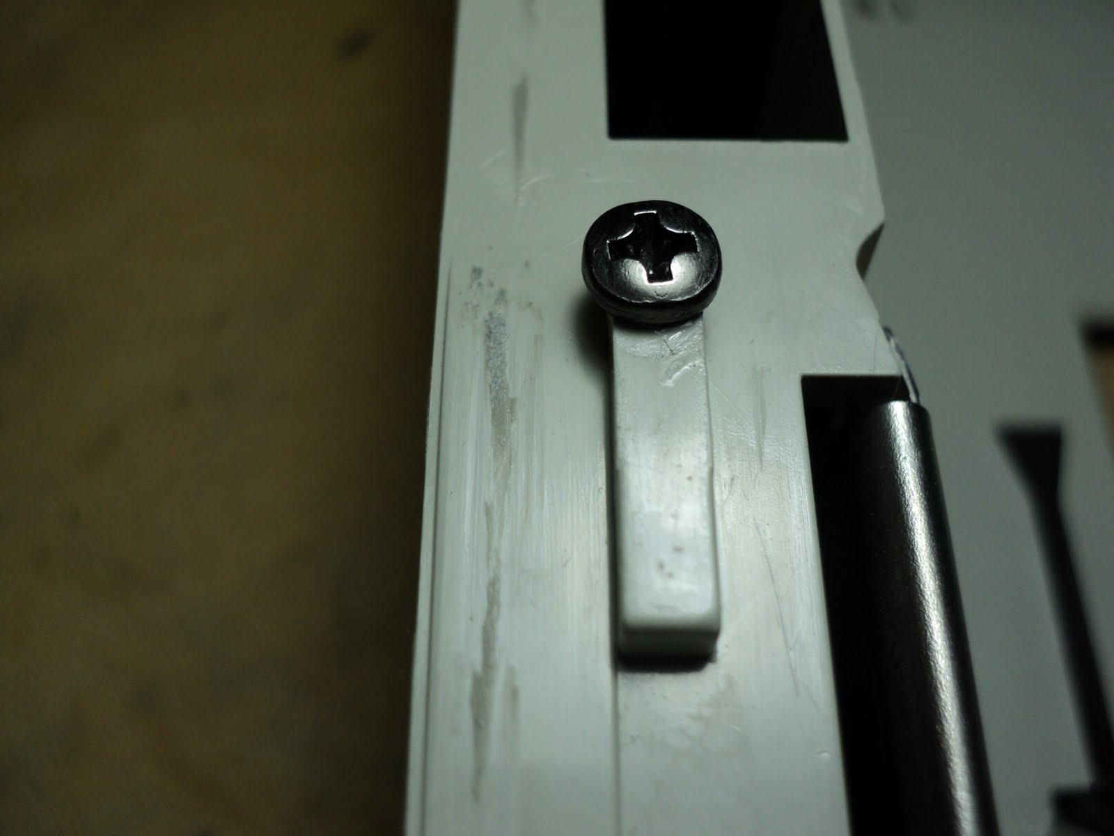
What the screw head does is it provides a lever actuation surface that deflects the lever without ever getting underneath its end. A drawer with this modification done to it will never wedge under a lever and break it.

One last tip -- wipe the drawer slides with WD-40 and you'll have a drawer with a much nicer action to it.

# # #


# # #

Wednesday, October 26, 2011

Lexmark T Series -- Label Sheet Feeding

Sheets of labels can be troublesome for pickup rollers because of their relatively slick surface on the back. Even new pickup rollers can experience traction failures on them. There is some traction force adjustability in Lexmark's autocompensator arms that may help. Here's a view of it in a T640 add-on tray.

The light spring that extends down the upper side of the autocompensator arm is a counterbalance spring. It's there to limit the pressure the pickup tires can exert when they're turning, so that multiple pickups don't occur.

Note the clip that anchors the end of the spring -- that clip's position is the adjustment. The clip in the above photo is set at design centre.

For trays that feed label sheets, move the anchor clip to its uppermost/rearmost position, as in the following photo.

That minimizes the spring's counterbalancing effect, maximizing traction. (On the T640 and T650 integral trays, the clip has been deleted; there's a series of holes along the top of the arm that provide the same adjustability.)

I ran the pictured tray with ordinary paper after adjusting it for maximum traction, and had no double-feeding occur.

For label sheets, it's also wise to avoid third-party pickup rollers. From what I've seen of them, they just don't have the traction of the OEM parts -- either 40X0070 or 40X4308.

# # #


# # #

Tuesday, October 25, 2011

Lexmark T Series -- Bad Fuser Roller Bearings


There's a no-name, third-party make of sealed ball bearings for Lexmark's T Series coated fuser rollers that's very prone to seize up. The bearings have no markings on them whatsoever. They have a distinctive appearance, though, so they're easy to identify. Here's a shot of them.


Both those bearings are completely seized. The seals are easily removed to reveal what's inside, and it's not pretty.

The grease the manufacturer uses is just not up to the job. What you see inside these bearings when they fail is 'grease' that's all but completely solidified -- there's no lubricant left at all.

Fuser roller bearings lead a hard life. They run hot, and the radial load on them is high because of the pressure roller.

Best to stick with the OEM part (Lexmark P/N 99A0143), or a 6003Z bearing that you know has grease in it that's suitable for this application.

- - -

Addendum -- FRIDAY, NOVEMBER 4, 2011

Here's a photograph of a worst-case bearing seizure.


When a bearing seizes, the coated roller continues to turn in the thermal isolation bushing. Eventually, the bushing wears through and you get metal-on-metal rotation. Here's a view of the outcome.


# # #


# # #

Thread-Forming Screws

Around here, no detail is too insignificant or obscure to go unremarked upon, so here's a little item about thread-forming screws you may not be aware of.

- - -

Thread-forming screws are widely used in the chassis of printers wherever things are fastened to plastic. They don't 'cut' a thread, they form a thread by displacing and compressing the plastic material as they're first run in at the factory.

You may have noticed when reinstalling such screws that you've removed, that sometimes they run back in easily; sometimes not so easily. There's a reason for that.

It's too fine a detail to photograph well, but for what it's worth, here's a shot of two typical screws from a Lexmark top cover.

If you examine the threads closely, you'll see that the threads are double helices, aka 'two-start' threads. I suspect that there's a limitation inherent to the screws' manufacturing process, because the threads are never perfectly symmetrical and uniform.

The upshot of that is that when you happen to start a screw with the same orientation it had at the factory when it was first installed, the screw will run in easily. When you happen to start a screw 180° around from its original orientation, the screw will meet resistance.

Try this the next time you start in a screw and get resistance -- carefully back the screw out until it 'clicks over' to the other one of its two 'starts'; the screw will then likely run in easily. The difference can be quite pronounced.

# # #

Lexmark T63X -- Noisy Fuser Cleaning Wand

From the "just when you think you've seen everything" department, comes this freakish incident.

A very clean T630 with a low maintenance count came in the shop. I set it to running off some test prints, and it made quite a loud moaning/squealing noise.

Removing the felt fuser cleaning wand made the noise go away. [!?]

I've let the machine go with a bit of trepidation; I can't help but wonder if there's more to that noise than met the eye, so to speak. Noises in rotating machinery can be extremely deceptive, and difficult to track down to their real source. We'll see if that's the end of it, or if it bounces back soon with the same complaint.

# # #

Monday, October 24, 2011

Lexmark T64X -- Config Menu

Much of what's in the Config Menu is of little, if any, use. The few useful items below are headed in bold.

To invoke the Config Menu, press and hold the 'check mark' and 'right arrow' keys while powering on the printer. You can let go of the keys as soon as you see dots begin to crawl across the display. Following are the items in the menu.

1) Maint Cnt Value
  • Displays the accumulated page count since the last time the maintenance counter was reset. This count is what the machine uses to determine when to display the '80 Scheduled Maintenance' message. (Maintenance interval is 300,000 pages.) Resetting the maintenance count (following item) clears the '80...' message.
2) Reset Maint Cnt
  • When selected, the maintenance count gets reset to zero. The maintenance count can be reset at any time.
3) Prt Quality Pgs
  • Prints four pages: a page of printer information, a greyscale page, a solid black page and a blank page.
  • WARNING: The solid black page can adhere to a fuser's coated roller and jam. The 'Prt Quality Pgs' are really not useful. We advise they be avoided.
4) Size Sensing
  • Allows you to disable the auto size sensing feature for the paper tray(s). This can be helpful if you encounter a machine that's exhibiting flaky size sensing. See this post for more information.
5) Panel Menus
  • Allows you to disable/enable a user's access to the menus. When disabled, pressing the 'Menu' key brings up the message, 'Menus are Disabled'.
6) PPDS Emulation
  • 'PPDS' stands for 'Personal Printer Data Stream', an early IBM printer command language. (It was originally called 'IBM ASCII'.) You're unlikely to ever encounter a site where it's used. If this emulation were enabled where it's not in use, the printer would likely print gibberish, if it printed at all.
7) Demo Mode
  • Useless, really. When Demo Mode is activated, all the machine will do is print a demo page; it won't go on-line, and the Menu key is disabled.
8) Factory Defaults
  • On a network-ready machine, you'll get the option to 'Restore Base' or 'Restore Network'
  • Restores all the pertinent menu settings to their factory defaults.
9) Energy Conserve
  • Allows you to enable disabling of the Power Saver feature. [I know that sounds odd, but that's what it does.] Power Saver is an item in the user's Setup Menu. (Select 'Settings' from the Main Menu to get to it.) When Energy Conserve is 'on', Power Saver can't be disabled, it can only be adjusted for delay time. When Energy Conserve is 'off', Power Saver can be disabled, as well as adjusted for delay time.
10) Event Log
  • Allows you only to print an abbreviated version of the event log.
11) Paper Prompts
  • Allows you to alter the machine's reporting of out-of-paper conditions. The settings are 'Auto', 'MP Feeder' and 'Manual Paper'. I've never had need of this.
12) Env Prompts
  • Allows you to alter the machine's reporting of out-of-envelope conditions. The settings are 'Auto', 'MP Feeder' and 'Manual Env'. I've never had need of this.
13) Jobs on Disk
  • Only shows up if the printer has a hard drive. Allows you to delete jobs stored on the drive. This might be useful in the event that a hard drive got loaded up with garbage that needed to be purged.
14) Disk Encryption
  • Only shows up if the printer has a hard drive. Allows you to enable or disable encryption.
  • WARNING: Changing the setting wipes the drive.
15) Font Sharpening
  • I've read the entry on this in the service manual, and I'm still mystified. I strongly suspect that whoever wrote the entry in the service manual is equally mystified.[1] It sounds like it has something to with adjusting print quality. I've never needed to look into it.
16) Wiper Message
  • Allows you to enable or disable the wiper message. I cannot find an explanation of what governs appearance of the wiper message.
17) Exit Config Menu
  • Does an orderly exit and returns the machine to 'Ready'.
* * *

Note [1]: Here's the service manual's complete entry on 'Font Sharpening':

"This setting allows a user to set a text point size below which the high frequency screens are used when printing font data. For example, at the default 24, all text in font sizes 24 and less will use the high frequency screens. The values for this setting range from 0 to 150, and the default value is 24. This setting affects Post Script, PCL, and XL.

To change the value, select Font Sharpening from the CONFIG MENU, and use [left arrow] to decrease the value and [right arrow] to increase the value. [Check mark] to accept the value."

- - -

I'm pretty certain that the 'technical writer' who wrote that hadn't a clue what they were on about, but they had to write something about Font Sharpening, so they did.

Whenever you see a term like 'high frequency screens' tossed out with no word of explanation, as if the term were as common and broadly understood as the word 'table' or 'chair', you know you're reading hogwash. Service manuals are riddled with that sort of tripe. 'Studying' such nonsense is a waste of time. I'll refrain from getting going on codswallop like PDI+ Certification.

# # #

Friday, October 21, 2011

Lexmark T Series -- Bevel Gear Replacement

The bevel gear that drives the vertical power-take-off (PTO) shaft for add-on trays occasionally breaks, or wears at its upper bearing so badly that it loses mesh. Pictured below is the gear in place at the front of the drive-train.

The method for removing and replacing it is a bit odd, but it does work and nothing ever breaks, even though it seems at times that something might.

To remove the gear, first pull the vertical PTO shaft w/spring out through the bottom of the printer. Then place your thumbs on the upper surface of the protruding bevel gear and press downward forcefully. The top end of the gear will pop out of its bearing. Here's a view of the gear having just been dislodged.

Note the thrust washer. Printers that have an add-on tray installed experience a constant upward thrust on the gear. Prior to the addition of the thrust washer, the gears would tend to wear quite badly where they rode in the upper bearing. The gear would keep moving upward until it would lose mesh. When installing a replacement gear, grease the upper end of it liberally.

To install the gear, get it into position so its upper end is nudged up against the upper bearing's opening, get your thumbs on the gear's teeth and press upward and inward forcefully. The gear will snap into place. Make certain that it's all the way up. When the gear is correctly installed, its lower end is concealed by the lower bearing, as in the first photograph above. Reinstall the drive-shaft w/spring and you're done.

# # #

Lexmark T64X -- Catastrophic Fuser Roller Failure

When you can see daylight between a fuser's rollers, you know something is amiss.

Here's a view of it with the cover removed.

Metal fatigue, I guess. Where the reduced-diameter end of the roller meets the body of the roller, there's not a great deal of material. Here's a close-up of the broken-off end.

The rest of the fuser was ok. Sometimes, a broken fuser roller will cause the thermal fuse to go open.

This fuser had gotten a new pressure roller and pressure roller bearings only 1,300 pages ago. The coated roller had looked fine at the time, so there's no way you can see this coming.

I put a new roller in the fuser and it's good to go.

# # #

Thursday, October 20, 2011

Lexmark T63X -- Fuser Teardown/Overhaul

[NOTE: There's a condensed, 'checklist' version of this document here.]

Proceed as follows:

1) Left Side Lamp Terminal Cover
- Two M3x6mm pan head screws.
- One rearward-gripping claw.

2) Left Side Lamp Terminal

NOTE 1: The screw w/captive washer at the electrical connection is sometimes extremely tight, and the plastic will break nearby before the screw breaks loose. To prevent this from happening, grasp the plastic on either side of the screw head with slip-joint pliers, and support it as you torque the screw to loosen it.

- One M3x6mm pan head screw at plastic base.
- One M3x5mm screw w/captive washer at electrical connection.

NOTE 2: Scrape the lamp contact's surfaces where it contacts the lamp terminal with a small screwdriver. The contact surfaces must be clean and bright. Contacts that show evidence of arcing and can't be easily made clean and bright must be replaced.

3) Lamp
- Only handle the lamp with a paper towel around it; the lamp's surface should not be touched. If a lamp does get anything oily on it, clean it w/methyl hydrate.
- Burnish the lamp's contacts with synthetic steel wool. Pitted contacts that cannot be made clean and bright call for replacement of the lamp.

4) Thermistor Cable
- Cut and discard the ty-wrap.
- Unplug it and free it from its restraints.
- When installing a new ty-wrap, leave the thermistor cable out of it. Only bundle the other three small cables.

5) AC Spade Connector at the upper right of the top cover
- Disconnect it, and clean up any oily residue there.

6) Top Cover
- Two M3x6mm pan head screws.
- Check that the thermal fuse's screws are snug.

7) Stripper Bar Torsion Springs

8) Exit Roller
- Two self-latching bearings.
- NOTE that the flanged gear must mesh with the idler gear; the flange is the idler gear’s retainer.

9) Idler Gear

10) Pressure Roller Springs
- Unhook them at the lower front of the frame.

11) Ring Gear
- One external snap-ring.

12) Left Side Bearing[1]

13) Hot Roller w/Bushings[1]

14) Right Side Bearing[1]

15) Input Ramp
- Spread the sides of the frame A/R to free it.

16) Stripper Bar
- Spread the sides of the frame A/R to free it.

17) Pressure Roller w/Bearings and Bearing Holders[2]
- NOTE: Any evidence of flat-spotting or delamination is cause to replace this roller. A flat-spot will cause a thumping noise; delamination will only get worse.

- - -

At this point, you can proceed in either of two ways.

a) Carry on with the full procedure for a thorough overhaul.

b) Abbreviate the procedure for a 'good-enough' overhaul.
- Scrape the right side lamp contact.
- Blow out the lamp contact and the sensors w/compressed air.
- Apply a couple of drops of light mineral oil to the pressure roller arms' pivot points.
- Inspect the two sensors.
- Reassemble w/new parts A/R.

- - -

18) Output Ramp
- Two sensor cable connections.
- Spread the sides of the frame A/R to free it.
- Examine the sensor toggles. They must move freely and return to their upright positions smartly. Any tendency for them to bind or stick will result in paper jam errors

19) Pressure Roller Springs

20) Right Side Pressure Roller Arm[3]
- One E-Clip.

21) Left Side Pressure Roller Arm and Link[3]
- One E-Clip.

NOTE: The following three steps complete the tear-down, but for reasonably clean units they can be dispensed with. Only proceed with them for units with dirty frames that need to be washed. Whether you remove it or not, examine and scrape the right side lamp contact as was done for the left side contact.

22) Right Side Lamp Contact Assembly
- Two M3x6mm pan head screws.
- One bulkhead connector.

23) PCA
- Solenoid cable connection.
- Two M3x6mm pan head screws.

24) Solenoid
- One M3x6mm pan head screw.


26) Reassemble w/new parts A/R

- - -

Notes

[1] Re Hot Roller and bearings:

Hot rollers can look pretty bad but still work fine. That said, any hot roller that's not in perfect condition should be replaced for longest service life of the fuser.

Bearings that turn freely but with a slight feel of grease resistance to them are ok to re-use. Bearings that spin very freely are likely grease-starved and should be replaced. If at all in doubt, replace the bearings; there's really no way to judge life expectancy.

[2] Re pressure roller and bearings:

Rusty looking spindle ends indicate that the roller has been turning in seizing or seized bearings. Both the roller and its bearings must be replaced, even if the roller looks fine otherwise.

Bearings that turn smoothly and exhibit a bit of grease seepage are ok to re-use but, again, there's really no way to judge bearing life expectancy. These bearings are fairly heavily loaded for their size. Unconditional replacement is probably the best practice.

[3] Re Pressure Roller Arm Pivots

The grease applied at the factory does not age well. It turns to a stiff sludge that interferes with the arms' freedom to pivot as they should. It takes lacquer thinner and a small brass-bristled brush to get the pivots clean.

Grease the pivots and the ends of the solenoid link at reassembly. The grease we use is Lubriplate No. 930-AA.


- - -

Frequently Replaced Parts

Assembly, 115V Fuser, T630/632: P/N 56P2542 [was 56P1333]

Assembly, 115V Fuser, T634: P/N 56P2545 [was 56P1859]

Bearing, Hot Roll [6003Z: 17mm bore x 35mm O.D. x 10mm thick]: P/N 99A0143

Bearing, Pressure Roller [R3Z: 0.1875" bore x 0.500" O.D. x 0.196" thick]: P/N 99A1621

Pressure Roller: P/N 99A0158-CLT

Coated (Hot) Roller: P/N 99A2036-CLT

# # #


# # #

Lexmark T64X -- Control Panel Replacement

The control panel in the T64X models is one of three items in the machine that has non-volatile RAM (NVRAM) on it. See this post for an explanation, and important information on dealing with it correctly. (The Control Panel's P/N is 40X0195.)

Control panel access on the earlier T models was a breeze. On the T64X it's an awkward chore.

- - -

Proceed as follows:

1) Paper Support
- Tip it up to about a 45 degree angle and tug it off its hinge pins.

2) Control Panel Cover & Window
- Two M2x8mm washerhead screws from in behind (they're No.1 Phillips recess).
- Tug forcefully at the upper rear lip and the cover will come away.
- The window is free to be removed once the cover is off.

3) Toner Cartridge Access Door Cover w/Control Panel
- One M3x10mm washerhead threading screw at the centre.
- Two M3.5x 9mm threading screws w/captive washers at the lower left and right.
- NOTE that the screw at the extreme lower left can remain in place.
- The cover has four 'hooks' near its upper edge that retain it quite securely. Tug the cover's lower edge upward and toward you to free them.
- Two cable connections.[1]
- NOTE the 'hook' arrangement for the cable at the left.

4) Control Panel
- NOTE: If you 'bridge' the Toner Cartridge Access Door Door Cover assembly across an open cardboard carton, the buttons won't get dislodged when you take away the Control Panel.
- Seven M3x8mm washerhead threading screws.
- NOTE that there's a roughly 'central' screw location that isn't used.

- - -

To fully dismantle the door cover for washing or whatever:

1) Latchbar w/Spring
- One M3.5x 9mm threading screw w/captive washer.

2) USB Connection PCA
- One M3x8mm washerhead threading screw.
- One claw.

3) Two Keypad Membranes

4) One Key Array

5) Three Individual Buttons
- NOTE how they're 'keyed' for correct reassembly.

6) One 'Lens'

The five buttons at the centre can remain in place, even for washing.

- - -
Note

[1] The cable at the right for the USB connection usually has a big ferrite bead on it that can be awkward to deal with when the cover is being reinstalled. Machines without the ferrite bead are probably from early production.

# # #


# # #

Wednesday, October 19, 2011

Lexmark T64X -- Redundant NVRAM

Lexmark's early Optra T printers experienced a lot of non-volatile RAM (NVRAM) failures ("954 NVRAM Failure" error message). There was only a single NVRAM IC in the machine and it was on the Engine Controller PCA, so that was straightforward enough -- replacing the Engine Controller PCA was the fix.

I imagine all those failures were what led Lexmark to build redundant NVRAM into the T64X models. Those machines all have three NVRAM ICs -- one on the System PCA, one on the Interconnect PCA and one on the Control Panel PCA. With NVRAM data existing in triplicate, an error from one NVRAM IC can be worked around and the printer can go on operating normally, instead of succumbing to a fatal error as the early Optra Ts did. All well and good, but it introduces a little servicing wrinkle that can make for some costly, clumsy repairs.

When any one of those three PCAs is replaced[1] for whatever reason, once initialized in a given machine, the replacement PCA is 'married' to that machine. It can't be used elsewhere; it can only stay where it is, or go back to the factory.

That can be a bit sticky when you have a coin-toss/guesswork troubleshooting situation; e.g. a printer that powers up with a blank display.

On the face of it, the fault is probably in the Control Panel PCA, but it's entirely possible for it to be in the System PCA. All you can do in that situation is quote the customer for the total cost of replacing both[1] parts, because that's what you may end up doing to fix the printer.

- - -

[1] Only replace one item at a time; the printer must have access to two of its original NVRAMs to be able to initialize the replacement part. Replacing two items at once will render the machine unrecoverably inoperative. Each part installed must immediately be put through a full power-on reset (POR) routine.

# # #

Tuesday, October 18, 2011

HP LaserJet 40X0 -- Fuser Overhaul

Proceed as follows:

1) Rear Cover w/Captive Screws
- One claw at right side end.
- One claw low at centre.
- One claw at left side end.

2) Top Cover
- Two M3x4mm bright washerhead screws.
- Two tabs, one at either side. A spring hook is helpful for levering them free.
- NOTE the tab-and-slot engagement at the centre-front of the cover.

3) Exit Sensor Toggle/Flag

4) Gear Train Cover
- Two M3x4mm bright washerhead screws.

5) Dark Front Gear (33t; P/N RS5-0921)

6) Dark Middle Gear (34t; P/N RS5-0922)

7) Outermost White Gear (21t; P/N RS5-0924)

8) Lower White Tandem Gear (16/18t; P/N RS5-0923)
- NOTE that the smaller end goes inboard.

9) Inboard Upper White Gear (26t; P/N RS5-0925)

10) Diverter Lever w/Torsion Spring
- One claw.

11) Diverter
- Spread the frame a bit to free its left side end.

12) Pinch Roller Frame P/N RB1-8799
- Spread the frame a bit to free it.

13) Thermistor Connector
- One claw. There's very little slack in the cable, but enough that the connector can be taken off.

14) Fuser AC Cable
- Disconnect the white connector at the lower right.

14) Fuser Film Sleeve Assembly P/N RG5-4290
- Lift it out.

15) Pressure Roller P/N RB9-0684 (was P/N RB1-8794)
- Lift it out,
- Left Side Bearing P/N RS5-1310.
- Right Side Bearing P/N RS5-1297.

- - -

That's typically as far as you need go.

Best practice is to replace the film sleeve assembly outright with a new OEM part. Replacement sleeves are available, though. Following is the procedure for replacing a sleeve.

- - -

Sleeve Replacement

1) End Cap at Thermistor Connector End
- Slip it out.

2) Sleeve
- Slip it off.
- NOTE that one end of the sleeve has a dark band. That's the thermistor connector end.

3) Clean the grease from the end caps and the heater body.
- Varsol is helpful as a solvent, but you don't want to soak the assembly in it. Wipe away as much grease as you can with paper towelling. Use Varsol sparingly to get all of it. A toothbrush is helpful. The parts should all be immaculately clean before the new sleeve is installed.

4) Apply silicone grease sparingly to the end caps, and lay a film of grease down the length of the heater. Here's more-or-less how it ought to look.

Slide on the new sleeve (black band at thermistor connector end), install the end cap, give the sleeve a turn or two and wipe away any squeeze-out that appears at the ends.

Reassemble the fuser w/other new parts A/R.

# # #

Monday, October 17, 2011

HP LaserJet 40X0 -- Routine Teardown/Overhaul

What follows is for a basic LaserJet 4000 with a single 500-sheet Tray 2.

1) Cartridge

2) Tray 2

3) Tray 2 Rear End Cover, if present

4) Fuser End Caps
- Tug their lower edges out and up.

5) Back Door
- Open it and pry at the right side hinge to free the door.

6) Fuser
- Two captive screws.

7) Rear Right Side Cover
- Tug it rearward to remove it.

8) Control Panel Overlay
- Pry at its right side lip to free two small claws.

9) Control Panel
- Pry up its front edge and two claws will let go. If the claws don't let go readily, you may need to coax them individually; they're down at either side near the front.
- One cable connection.

10) Top Cover
- Two M4x12mm bright pan head threading screws at the back.
- Two M4x12mm bright pan head threading screws under the toner cartridge access door.
- Cartridge engagement arm -- free its upper end.
- Pry at the right front to free the right front corner.
- Tug the front of the cover up forcefully to free it.
- NOTE: The door's hinges are easily separated to facilitate washing the door and cover.

11) Front Right side Cover
- One claw at the top.

12) Left Side Cover
- One claw high up rear of centre.

13) Tray 1 Door
- Pry gently to free the inner platform from its ways.
- Slide the door rightward off its hinges.

14) Tray 1 Platform w/Sensor Arm Cover and Torsion Spring
- Torsion spring. (Not present on early machines. Later machines have a torsion spring associated with the right side hinge.) Free it from the underside of the platform.
- Tug forcefully on the sensor arm cover to pop it off the pickup shaft.

15) Two Black Extended Head Screws near the Front
- The left side screw is visible by the violet cable for Tray 1's paper-out sensor.
- The right side screw is concealed under the envelope feeder's connector cover. Open the cover and you'll see the screw's head.

16) Tray 1 Pickup Assembly w/Left Side Cartridge Guide
- One in-line cable connection for the pickup solenoid.
- One cable connection for the paper-out sensor.
- Five M4x12mm black pan head threading screws in front. Four of them are in deep wells.

17) Paper Feed Assembly
- One in-line cable connection.
- Two M4x10mm black pan head threading screws. NOTE that these are in the upper holes of the brackets. The two lower holes are where two of the Tray 1 pickup assembly's screws go.

18) Cover-Open Switch Bracket
- One M3x6mm bright pan head screw w/captive star washer at blue ground wire terminal.
- One M4x10mm black pan head threading screw forward of and below the previous screw.
- Free the bracket and let it dangle by the side of the machine.

19) Registration Assembly
- One M3x6mm bright pan head screw w/captive star washer at the extreme right.
- NOTE. There is another M3 screw forward of and to the left of the previous screw. DO NOT loosen it.
- Five M4x10mm black pan head threading screws.
- Overhaul per this post.

20) Pre-Transfer Ground Plate
- Lift it out.

21) Delivery Assembly
- The left side white bearing unhooks easily and lifts out.
- The right side bronze bearing has a lever on it. Swing the lever up to vertical and the unit can be lifted out.
- Overhaul per this post. (Scroll down to "To dismantle...".)

22) Printhead
- Three cable connections.
- Four M4x12mm black pan head threading screws.

23) Formatter Cage
- Four M3x6mm bright washerhead screws. (Early machines had a fifth screw at the top.)
- Tug the cage rearward to disconnect it.

24) Formatter Cage Receiver (Sheet Metal)
- Four M4x10mm black pan head threading screws.
- Three M3x6mm bright pan head screws w/captive star washers or washerhead screws.

25) Fourteen-Conductor Cable Connector
- Unplug it and free it from its hook.

26) One M4x10mm Black Pan Head Threading Screw
- It's at the left side, just below and behind the lower rear corner of the fan.

27) Engine Chassis
- It's free to be lifted off the paper tray module.

28) Tray 2 Top Cover
- Two M3x6mm black pan head screws.
- Seven M4x10mm black pan head threading screws.

29) Tray 2 Pickup Assembly
- One M3x16mm black pan head threading screw, very low down in a notch at the right side.
- NOTE: The screw was deleted from later production.
- One two-conductor cable connection. Free the black cable from its restraints.
- Clean/replace rollers A/R.

30) PCA Cover
- Two claws at the top edge.

31) PCA
- Two cable connections.
- Two claws.
- Apply WD-40 to the pushbutton switches and actuate them many times. Blow them out w/compressed air.

32) Blow out and clean the base A/R.

33) Reassemble the tray module.

34) Blow out the engine's chassis with compressed air.

35) Reinstall the chassis on the tray module.

36) Reassemble from step '26)'.

# # #

HP LaserJet 4+/5 -- Fuser Overhaul

[The LaserJet 4's fuser is very similar, but many part numbers are different.]

Proceed as follows:

1) Cover, Upper Front (P/N RF5-0738)
- Two outward-gripping claws low in front, accessible via rectangular openings.
- Four claws high up.
- NOTE: This part is liable to have become brittle with age and break as it's removed.

2) Red and White Wire Terminals at Upper Front
- Two M3x6mm bright pan head screws w/captive washers.
- Free the red wire from its channel.

3) Two Coil Springs at Upper Rear

4) Thermistor Cable
- Unplug it and free it from its channel.

5) 90° Spade Terminal
- Disconnect it.
- NOTE: This is a locking terminal. There's a little lock button in the centre of the female terminal. You need to push on that with the point of a scriber to free the terminal.
- Free the long white wire from its channel.

6) Right Side Black End Cap (P/N RF5-0736)
- One M3 shoulder screw w/wavy washer at upper front.
- One M3x6mm bright pan head screw w/captive washers at lower rear.

7) Upper Gear (23t -- P/N RS5-0393)

8) Lower Gear (19t -- P/N RS5-0231)

9) Left Side Black End Cap (P/N RF5-0737)
- One M3 shoulder screw w/wavy washer at centre front.
- One M3x6mm bright pan head screw w/captive washers at lower rear.

10) Left Side Pressure Release Lever, if present
- P/N RB1-3523.

11) Lamp (P/N RH7-4054)
- NOTE that the red wire is at the left side.
- Room temperature resistance is approx. 1.6 ohms.

12) Thermal Fuse Block (P/N RG5-0881)
- One claw.
- Slide it rightward to free it.

13) Thermistor Cable Receptacle/Cable
- Free it from its restraints.
- NOTE that the slotted side of the receptacle faces forward.

14) Entry Ramp (P/N RB1-3518)
- Two claws -- it slides out the front.

15) Top Cover (Sheet Metal)
- Two tabs at the rear. It pivots up and comes away.
- NOTE: The thermistor is P/N RH7-7054. Room temperature resistance is approx. 260 kohms.

16) Ring Gear (42t -- P/N RS5-0388)
- One snap ring.

17) Right Side Pressure Release Lever, if present.
- Right Side P/N RB1-3527.

18) Coated Roller (P/N RB1-3516)
- NOTE: You'll need to wedge the pressure roller away from the coated roller to remove this part safely. Force each end of the pressure roller downward and insert the end of a 10-32 or 5mm screw to hold down the bearing.
- Carefully slide the roller out through its left side bearing.
- Remove the two screws.
- NOTE the slip ring and snap ring that must be transferred to a new roller when this roller is replaced.

19) Upper Rear Black Bar (Separation Guide -- P/N RF5-0744)
- Spread the frame a little to free it.
- REINSTALLATION NOTE: The exit sensor toggle must end up behind the pivoting bar.
- NOTE: The exit sensor toggle is P/N RB1-3522.

20) Right Side Coated Roller Bearing (w/one hole and one slot -- P/N RS5-1097)
- One M3x6mm bright washerhead screw.

21) Left Side Coated Roller Bearing (w/two holes -- P/N RS5-1098)
- One M3x6mm bright washerhead screw.

22) Pressure Roller and Bearings
- Each bearing P/N RS5-1099.
- Pressure Roller P/N RB1-3517.

23) Pivoting Bar w/Torsion Spring (Lower Separation Guide)
- NOTE the bar's relationship to the two stop tabs on the vertical portions of the frame.
- One M3 shoulder screw.

- - -

Clean all parts A/R.

Reassemble w/new parts A/R.

# # #

Sunday, October 16, 2011

The Written Word and 'Class'

Working in business-machine/computer repair shops as I have all my working life, I've noticed a peculiarity of how service manual 'libraries' are kept; they're always kept at a distant remove from the technicians who actually have need of the things. They're invariably kept in a front-office space somewhere, not in the shop where they'd be right handy to the technicians. Odd, eh? Counter-productive/counter-intuitive? I think I may have divined the reason for it.

The service manuals contain written words, and the written word is the province of the intellect. Management is loath to concede that there could possibly be an intellectual dimension to the work that technicians do. So, the service manuals must be kept where they're readily accessible to those 'intellectuals' who have no use for them; not where they're readily accessible to those 'grunts' who do have use for them.

It all makes perfect sense, once you acknowledge the 'class' structure that's at work. 'Classless society'? Yeah, right,

Am I bitter about it? Not at all. I'm so far past giving a shit, I could be be in a workshop in the Yukon, while a service manual I need is in an office in Prince Edward Island, and I wouldn't give a shit.

Management, you're welcome to your membership in a superior class. I'm sure you're entitled to it. And here's my 'working class' anthem in response to your 'superiority'.

- - -

Addendum -- SUNDAY, OCTOBER 16, 2011

There's a noteworthy corollary to what I've just said above. The content of those service manuals is written not by those who actually know and understand the machinery, it's written by low-end members of the 'intellectual' class. They're the ones with the credentials to qualify themselves to be hired as technical writers. Consequently, the content of the service manuals is, by and large, not worth the powder to blow it to hell.

Do we have a great system here or what?

# # #

Friday, October 14, 2011

HP LaserJet 40X0 -- Vertically Elongated Prints

We've only seen this once, and it had us going for awhile -- it was a baffling symptom. A LaserJet 4000 was giving prints that were 'stretched out' a bit vertically. The user's application was critical for vertical registration and positioning throughout the length of a page, so he couldn't live with it.

At first, we thought it was a vertical registration (top margin) problem, but adjusting that didn't alter the elongation.

It turned out that it was caused by slightly swollen rubber rollers on both the registration assembly and the paper feed assembly. The increased diameter of the rollers increased the linear speed of a sheet of paper as it went through transfer -- hence, an elongated print.

There are probably more machines out there that have the same problem, but most applications don't reveal it.

# # #

HP LaserJet 40X0 -- Registration Assembly Partial Overhaul

[NOTE: The following applies equally as well to the 4100.]

The bronze sleeve bearings that bear the lower roller tend to accumulate sludge and cease to be free-turning. (This post tells of an outright seizure we encountered.) The registration assembly is a clumsy thing to dismantle completely, but that's seldom necessary. If the upper nylon bearings are ok (they usually are), take apart just the lower roller for cleaning and lubrication; it's quite easy to do. Proceed as follows.

1) Gear
- One claw.

2) Two E-Clips on Lower Roller

3) Wedge the upper (pinch) roller up a bit with a small screwdriver at the left side end; the following will be much easier.

4) Left Side Bronze Bearing

5) Lower Roller

6) Right Side Bronze Bearing

Clean the gear and the bearings w/Varsol.

Clean the roller w/lacquer thinner.

Reassemble, and oil the bronze bearings sparingly w/light mineral oil.


# # #

HP LaserJet 40X0 -- Delivery Assembly

The LaserJet 40X0 delivery assembly is long lasting and reliable, but not entirely maintenance free. The unit is easy to tear down and overhaul.

To gain access to the delivery assembly, proceed as follows.

1) Back Door
- Open it.

2) Rear Right Side Cover
- Tug it rearward to remove it.

3) Control Panel Overlay
- Pry at its right side lip to free two small claws.

4) Control Panel
- Pry up its front edge and two claws will let go.
- One cable connection.

5) Top Cover
- Two M4x12mm bright pan head threading screws at the back.
- Two M4x12mm bright pan head threading screws under the toner cartridge access door.
- Cartridge engagement arm -- free its upper end.
- Pry at the right front to free the right front corner.
- Tug the front of the cover up forcefully to free it.

6) Left Side Cover (This can stay in place, but we prefer to have it out of the way.)
- One claw high up rear of centre.

7) Delivery Assembly
- The left side white bearing unhooks easily and lifts out.
- The right side bronze bearing has a lever on it. Swing the lever up to vertical and the unit can be lifted out.

- - -

To dismantle the assembly, proceed as follows:
[NOTE: The following applies as well to the 4100 delivery assembly.]

1) Upper Black Guide
- Disengage two tabs at the rear, one at each side.
- The unit clips onto the bearings' sleeves. Gently pry it off.

2) White Bearing
- Two claws. (On the 4100, this bearing just slides off.)

3) Gear
- One claw.

4) Bronze Bearing
- Slide it off.

4) Brass Washer
- Slide it off.
- Leave the e-clip in place. There's no need to remove it.

5) Two Upper Roller 'Riders'
- NOTE their orientation.
- Pry them off.

Overhaul

1) Dirty frames can be washed with hot water and Fantastik with their pinch rollers left in place. Blow the unit dry with compressed air.

2) Clean the gear and the white bearing's bore w/methyl hydrate.

3) Clean the brass washer and the bronze bearing's bore w/Varsol.

4) Clean the upper roller w/lacquer thinner.

5) Reassemble. Apply light mineral oil sparingly to the bronze bearing prior to installing the gear and the upper black guide.

Here's how the upper roller's 'riders' look when correctly in place.

The bronze bearing's axial position can seem a little ambiguous. It's supposed to go leftward against the brass washer and e-clip until the e-clip hits a stop. Here's how it should look.


The two 'riders' on the upper roller can be treacherous. Make certain they're pointing forward before snapping the upper black guide in place. It's easy to get them flipped around to where they block the paper path. Confirm that they're correctly oriented before reinstalling the assembly in the printer.

On reinstallation in the printer, note that there's a ground continuity leaf that extends rightward from the upper black guide. It's meant to contact the metal frame of the delivery drive-train as shown below.


Finally, confirm that the bin-full sensor's flag swings freely through the optical sensor's slot.

# # #

Thursday, October 13, 2011

HP LaserJet 40X0 -- 50.2 Fuser Error

"50.2" indicates that the fuser failed to warm up. Replacing the fuser is usually all it takes to solve the problem. Now and then, though, the error persists. When a printer with a known-good fuser in it gives this error, the fault is with the Engine Controller PCA. Proceed as follows to gain access to the PCA and replace it.

1) Cartridge

2) Tray 2

3) Fuser End Caps
- Tug their lower edges out and up.

4) Back Door
- Open it and pry at the right side hinge to free the door.

5) Fuser
- Two captive screws.

6) Rear Right Side Cover
- Tug it rearward to remove it.

7) Control Panel Overlay
- Pry at its right side lip to free two small claws.

8) Control Panel
- Pry up its front edge and two claws will let go.
- One cable connection.

9) Top Cover
- Two M4x12mm bright pan head threading screws at the back.
- Two M4x12mm bright pan head threading screws under the toner cartridge access door.
- Cartridge engagement arm -- free its upper end.
- Pry at the right front to free the right front corner.
- Tug the front of the cover up forcefully to free it.

10) Front Right side Cover
- One claw at the top.

11) Left Side Cover
- One claw high up rear of centre.

12) Two Black Extended Head Screws near the Front
- The left side screw is visible by the violet cable for Tray 1's paper-out sensor.
- The right side screw is concealed under the envelope feeder's connector cover. Open the cover and you'll see the screw's head.

13) Formatter Cage
- Four M3x6mm bright washerhead screws. (Early machines had a fifth screw at the top.)
- Tug the cage rearward to disconnect it.

14) Formatter Cage Receiver (Sheet Metal)
- Four M4x10mm black pan head threading screws.
- Three M3x6mm bright pan head screws w/captive star washers.

15) Fourteen-Conductor Cable Connector
- Unplug it and free it from its hook.

16) One M4x10mm Black Pan Head Threading Screw
- It's at the left side, just below and behind the lower rear corner of the fan.

17) Engine Assembly
- It's free to be lifted off the paper tray(s) module. Mind the Tray 1 door as you lift the engine off and set it upside down on a work surface.

18) Engine Controller PCA
- Switch Rod -- free its rear end from the switch lever on the PCA.
- Three M3x6mm dark pan head screws w/captive star washers. (They're pointed out by arrows.)
- Four M4x10mm black pan head threading screws. (They're pointed out by arrows.)
- One drum ground connection -- it's a torsion spring end near the front of the fan.
- Two cable connections at the fan side of the PCA.
- Tip up the fan side of the PCA.
- Ten conventional cable connections.
- One ribbon cable connection.

- - -

With the PCA out of the engine, it's a good time to blow out the engine with compressed air.

Take great care with reconnecting, repositioning and refastening the replacement PCA. Note that there are four high voltage spring-contacts at the fan side near the front. Those must not get distorted.

# # #

HP LaserJet 40X0 -- Fuser Continuity Test Points

Here's a view of the fuser's connector.


The large pin at the centre is tied to chassis ground.

The two large pins to the right are the heater's terminals -- approx. 13.6 ohms.

The two small pins nearest the large centre pin are the thermistor's terminals -- approx. 400 kohms at room temperature.

The remaining three small pins at the extreme left are the exit sensor's terminals.

# # #

Wednesday, October 12, 2011

Terminology -- Bearing/Bushing

One often sees the word 'bushing' used for what is in fact a 'bearing' -- a 'sleeve bearing'. It's an accepted usage, but it's a poor one that ought to be avoided.

The word 'bushing' is best reserved for items that merely take up the space between two different diameters. The following photograph gives a good illustration.

At the very left is one end of a coated fuser roller from a Lexmark T640. Next to it is the bushing that goes on the end of the roller for thermal isolation. Next to the bushing is the ball bearing that fits over the bushing.

The remaining two items are both bearings -- sleeve bearings.

Think of it this way, if a thing serves to bear the load of a rotating component, then it's a bearing. Bushings are just filler.

# # #

Tuesday, October 11, 2011

Lexmark T64X -- Fuser Cleaning Wand Cover Defect

The fuser cleaning wand cover on the T64X machines has six little claws that are meant to grip and carry the cleaning wand or cavity insert. Here's a photo of one that's still intact.[1]

The claws become brittle with age, and break off and fall into the fuser -- not helpful. The cover pictured below has lost two of its six claws.

Whenever you see this, take a pair of pliers and break off all the remaining claws. You'll save yourself some future aggravation.

- - -

[1] P/N is 40X0001. It comes as seen in the first photograph above, with a cavity insert attached.

# # #


# # #

Lexmark 917 Error

"917 Service Transfer Roll" is unlikely to be caused by anything other than the high voltage power supply (HVPS). There's a remote possibility that it could be caused by wiring/cabling, or even an engine controller or system PCA, but the odds are that it's the HVPS that's at fault.

The T64X series has been especially prone to give intermittent 917 errors. The P/N for a T64X HVPS is 40X4275.

This post gives the procedure for getting at the part to replace it. (It refers specifically to the T63X, but the T64X is virtually the same.)

# # #

Bronze Sleeve Bearing Seizures

An HP LaserJet 4050 came in the shop last week with the complaint that paper was consistently stopping at the registration roller. It turned out there was a good reason for that -- the registration roller had seized so badly in its bronze sleeve bearings that its gear had 'walked' off the end of the shaft a little, and was turning on the shaft to no effect. Here's a photo of the damaged gear.

And here's a view of one of the two bearings that was at fault.

This type of bearing is widely used in all makes and models of printers. Manufacturers love them because they're compact and inexpensive. They're also very durable, but they do require periodic attention, or they'll end up like the bearing shown above.

Seizures as bad as this one are relatively rare, but any machine that's seen lengthy service needs to have its sleeve bearings attended to. Long before a bearing seizes outright, it's likely to squeak and/or add load to the drive motor because it's no longer free-turning. That condition also leads to accelerated wear of gear teeth.

At the very least, apply WD-40 or light mineral oil. When a machine is being overhauled, all of its shafts borne in sleeve bearings should be dismantled, the shafts and bearings thoroughly cleaned, then oiled with light mineral oil on reassembly. (Nylon sleeve bearings needn't be oiled; just cleaned.)

Note that even a seizure like this is not end-of-life for the bearings. If I could get a replacement for the damaged gear, this registration assembly could be dismantled, cleaned, reassembled and oiled for lengthy service yet. Most sleeve bearings will actually last forever with periodic maintenance.

- - -

Addendum -- FRIDAY, OCTOBER 14, 2011

We took a closer look at the 'damaged' gear, and decided that it wasn't too far gone after all, provided that we glued it in place with CA adhesive. (The gear will never have to be removed again for the foreseeable life of the part.) Here's a shot of it after having dealt with the bearings and roller per this post.


# # #

Sensor Toggle Repairs

It's often possible to repair broken sensor toggles with solid copper wire and CA adhesive. Here's a repair made to a narrow-media sensor from a Lexmark T630 fuser.

18 AWG (0.0403" diameter) wire is substantial enough, yet relatively easy to form. Once you have the wire formed and in place, clean the item thoroughly with methyl hydrate, let it dry and apply CA adhesive so it wicks in everywhere between the copper wire and the plastic toggle. Take great care that the glue doesn't get away from you and foul the torsion spring or pivots. Leave the thing undisturbed for awhile for the glue to thoroughly harden.

On reinstalling the sensor, check that your repair's length/shape is ok and tweak it A/R. Here's a view of this sensor back in the machine.

I've done enough of these that I've seen machines return to the shop after considerable service with one of these repairs; this repair method appears to hold up fine.

# # #

Wednesday, October 5, 2011

HP LaserJet 5 -- Delivery Assembly Overhaul

The upper delivery roller is a weak point -- it tends to glaze and lose traction leading to 'accordian' jams in the back of the printer. Replace both rollers when overhauling an assembly.


- - -

Lower Roller P/N RF5-1077.

Upper Roller P/N RF5-1076.


- - -

1) Upper Black Guide[1]
- Two claws at the rear corners.
- The front of the guide hooks onto the upper roller's bearing sleeves. Pry gently to free it.

2) Timing Belt
- Slip it off the lower roller's pulley.

3) Lower Roller; Pinch Rollers; Springs
- One e-clip.
- One 5mm bore nylon bearing.
- Slip the roller's bronze bearing out of place to free the roller.
- Four pinch rollers.[2]
- Four pinch roller springs.

4) Upper Roller[1]
- One e-clip.
- One 6mm bore nylon bearing.
- Slip the roller's bronze bearing out of place to free the roller.

5) Belt/Pulley Assembly
- One extension spring.
- Lift the tab at the end of the pulley toggle to allow the toggle to turn fully CCW. The entire bracket w/pulley toggle and belt will be free to come away.
- NOTE the small rectangular opening in the lower end of the bracket. At reinstallation, that opening must first go over a mating projection on the plastic body of the unit.

6) Wash and dry (with compressed air) the body, the upper black guide and the belt/pulley assembly.

7) Clean the bores of the two nylon bearings w/methyl hydrate.

8) Lubricate the two pulley spindles sparingly with WD-40.

9) Reassemble with new upper and lower rollers.


- - -

Note [1]: The upper roller has four litle 'riders' on it. They're there to ensure that the trailing edge of an exiting sheet of paper falls away immediately as it exits. When reinstalling the upper black guide, take care to ensure that the riders all point forward as the guide is snapped into place.

Note [2]: The pinch rollers tend to accumulate toner and grime, but it has no ill effect. We don't bother cleaning them.


# # #

HP LaserJet 5 -- Routine Teardown/Overhaul

The LaserJet 5 is an excellent machine -- well worth what it may take to keep one going. Following is the order of work for a thorough teardown and cleaning/overhaul.


- - -

1) Cartridge

2) Tray 2

3) Right Side Cover
- One captive M4 screw at the upper rear.
- Slide the cover rearward a bit to free it.

4) Back Door

5) Top Cover
- Two M3x8mm pan head YZD screws w/captive washers at the upper rear.
- One M3x8mm pan head YZD screw w/captive washers under the toner cartridge access door.
- Tray 1 open.
- Two forward-gripping claws in front (rectangular openings -- 5mm x 17mm).
- Lift cover and tip up its left side.
- One cable connection at the control panel.

6) Tray 1 Door w/Platform Extension
- Pry gently at the inner platform ways to free the door from the inner platform.
- Slide the door rightward off its hinge pins.
- Flex the platform extension A/R to free it from its ways.

7) Left Side Cover
- One claw at upper rear near the front corner of the delivery assembly.
- Pry at the front lip to free it.

8) Right Front Cover
- One M3x8mm pan head YZD screw w/captive washers.
- One claw visible high up.
- One claw visible at the right side.
- One claw below the switch rocker -- accessible via an opening in the sheet metal.
- One claw at the lower left corner.

9) Delivery Assembly
- Ground continuity clip at upper left.
- Two claws low down at rear. Tip the unit up and remove it rearward.
- NOTE the two hooks at the lower front that must engage openings in the sheet metal on reinstallation.

10) Fuser
- Two M4x8mm hex head (7mm A/F) screws w/captive star washers.
- Tug the unit rearward to unplug/remove it.

11) Cross-Brace Below Tray 1 Platform
- Two M3x6mm bright washerhead screws.

12) Tray 1 Platform
- Unhook the torsion spring at the left side hinge.
- Tilt the item downward until it can slip off its flatted hinge pins.

13) Envelope Feeder Slot Cover
- Tug the arrow-marked 'handle' downward to free the cover.

14) Paper Input Unit
- Two cable connectors at the right front.
- Two M3x8mm YZD pan head screws w/captive washers at the right front.
- Three M3x6mm bright washerhead screws at the left side.
- Slide the unit out the front.

15) Memory Access Door
- One captive 4mm screw.

16) Formatter Assembly
- Six M3x6mm bright pan head screws w/captive washers.
- Pull the assembly rightward straight off its connector.

17) Right Side Lower Front Perforated Sheet Metal
- NOTE how this item supports the switch rod at its upper rear corner.
- Two M3x6mm bright washerhead screws.

18) Switch Rod
- NOTE that the longer bent-over end engages the switch in the power supply; the shorter end engages the rocker in front.

19) Power Supply
- Two cable connections.
- Two M3x6mm bright pan head screws w/captive star washers.
- Pull the assembly rightward to unplug it from the fuser AC connector.

20) Printhead (It's self-aligning. No adjustment is disturbed by removing it.)
- NOTE the black plastic shutter actuator at the front left corner of the printhead. The actuator's tip goes behind the shutter's projection.
- Three cable connections.
- Free the cabling from the two upper restraints.
- Four M3x14mm YZD pan head screws w/captive washers.

21) HVPS (The 'Black Box' underneath.)
- Two M3x8mm YZD pan head screws w/captive washers.
- Two claws at the rear.
- Pull the item straight off.

22) Motor
- One cable connection.
- Four M3x10mm YZD pan head screws w/captive washers.

23) Gearbox
- Two M3x6mm bright washerhead screws.
- NOTE: At reinstallation, take care to ensure that this item is correctly and fully seated before running in and tightening the two screws.

22) Right Side Tray 2 Way
- One M3x8mm YZD pan head screw w/captive washers.
- On claw below the fuser AC connector.

23) Left Side Tray 2 Way
- One M3x8mm black pan head threading screw.
- One lock-button. Press it in until the item can be slid rearward.


- - -
24) Blow out the chassis w/compressed air.

25) Reassemble w/replacement parts A/R.


# # #

HP LaserJet 5 -- Top Cover and Control Panel Disassembly

Top Cover

1) Control Panel Overlay
- Pry at right side edge to free two small claws.

2) Ground Continuity Leaf Spring
- One M3x8mm black pan head threading screw.

3) Control Panel
- Two claws at its rear edge.

4) Hinge-Securing Block
- One tab. Lift its rounded end with a tiny hook made from a paper clip.
- Slide the block rearward.

5) Toner Cartridge Access Door
- Free the right side hinge pin, then the left side.


- - -

Control Panel

1) PCA
- Eight M2x7mm pan head YZD threading screws (No. 1 Phillips recess).

The key array is a unit. Note that the 'Go' and 'Job Cancel' keycaps are removeable.


# # #