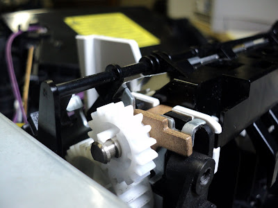
To gain access to the delivery assembly, proceed as follows.
1) Back Door
- Open it.
2) Rear Right Side Cover
- Tug it rearward to remove it.
3) Control Panel Overlay
- Pry at its right side lip to free two small claws.
4) Control Panel
- Pry up its front edge and two claws will let go.
- One cable connection.
5) Top Cover
- Two M4x12mm bright pan head threading screws at the back.
- Two M4x12mm bright pan head threading screws under the toner cartridge access door.
- Cartridge engagement arm -- free its upper end.
- Pry at the right front to free the right front corner.
- Tug the front of the cover up forcefully to free it.
6) Left Side Cover (This can stay in place, but we prefer to have it out of the way.)
- One claw high up rear of centre.
7) Delivery Assembly
- The left side white bearing unhooks easily and lifts out.
- The right side bronze bearing has a lever on it. Swing the lever up to vertical and the unit can be lifted out.
- - -
To dismantle the assembly, proceed as follows:
[NOTE: The following applies as well to the 4100 delivery assembly.]
1) Upper Black Guide
- Disengage two tabs at the rear, one at each side.
- The unit clips onto the bearings' sleeves. Gently pry it off.
2) White Bearing
- Two claws. (On the 4100, this bearing just slides off.)
3) Gear
- One claw.
4) Bronze Bearing
- Slide it off.
4) Brass Washer
- Slide it off.
- Leave the e-clip in place. There's no need to remove it.
5) Two Upper Roller 'Riders'
- NOTE their orientation.
- Pry them off.
Overhaul
1) Dirty frames can be washed with hot water and Fantastik with their pinch rollers left in place. Blow the unit dry with compressed air.
2) Clean the gear and the white bearing's bore w/methyl hydrate.
3) Clean the brass washer and the bronze bearing's bore w/Varsol.
4) Clean the upper roller w/lacquer thinner.
5) Reassemble. Apply light mineral oil sparingly to the bronze bearing prior to installing the gear and the upper black guide.
Here's how the upper roller's 'riders' look when correctly in place.
 The bronze bearing's axial position can seem a little ambiguous. It's supposed to go leftward against the brass washer and e-clip until the e-clip hits a stop. Here's how it should look.
The two 'riders' on the upper roller can be treacherous. Make certain they're pointing forward before snapping the upper black guide in place. It's easy to get them flipped around to where they block the paper path. Confirm that they're correctly oriented before reinstalling the assembly in the printer.
On reinstallation in the printer, note that there's a ground continuity leaf that extends rightward from the upper black guide. It's meant to contact the metal frame of the delivery drive-train as shown below.

Finally, confirm that the bin-full sensor's flag swings freely through the optical sensor's slot.
# # #
No comments:
Post a Comment