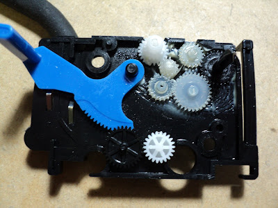
Replacing the gear case is not difficult, but there's a little booby-trap to be avoided. The following procedure begins with the space motor assembly already off the carriage frame, but still attached to the flat cable. Proceed as follows:
1) Flat Cable
- Unplug it and unhook the gear case claw at the right rear corner. Nudge the corner of the gear case upward a bit and the cable can be slid away. Here's a view of the cable part way off.
 2) Gear Case
- There are four claws altogether that secure the gear case to the space motor frame. Unhook the claws and the gear case can be lifted off the motor, but be careful; this is where the booby-trap enters into it.
The upper and lower halves of the gear case shell are lightly snap-fitted together. They separate easily. Careless removal of the gear case can result in a spill of its tiny components.
Here's a view of the gear case's interior.
 The small gear that shuttles back and forth to maintain unidirectional output has lost two teeth. The only reason I can think of for that to happen is that a ribbon cartridge may have seized while operating.
Anyway, this is from a relatively new printer, so I'm going to just replace that one damaged gear with one from a salvaged gear case. The rest of it is in fine condition, well lubricated with grease that's still fresh and effective.
- - -
That worked fine.
Always check printhead/platen gap after any carriage work on these printers. You might think you haven't done anything to disturb the adjustment, but it never seems to be correct after removing and reinstalling a space motor. The gap figure is 0.016" with the forms thickness lever all the way toward the platen.
- - -
Gear Case Operation
a) Forms Thickness Adjustment
The blue sector gear with the handle, along with the two gears down in front, act on the forms thickness adjustment screw (not seen in the photo). Moving the handle toward the front of the printer rotates the screw CW, increasing the printhead/platen gap.
The sector gear's handle has five detented positions, with position '1' being the single sheet setting (nearest the platen). Each detent-to-detent increment of sector gear rotation toward positon '5' turns the gap adjustment screw approximately 76 degrees CW, increasing the gap by 0.00275". The full range of sector gear rotation from position '1' through to position '5' increases the gap by 0.011". A gap that's been correctly adjusted for 0.016" at position '1' will become 0.027" at position '5'.[1]
b) Forms Thickness Setting Sensing
Note the two leaf-spring contacts in front of the blue lever. Their lower ends protrude beneath the gear case, where they're poised above contact pads on the space motor PCA. As the forms thickness setting is increased, those contacts make/break to inform the controller of the setting. There's a third, common contact between those two contacts that's always made.
The outboard (leftmost) contact is designated 'SW1'; the inboard contact is designated 'SW2'. Following are the switch states for the five thickness settings: (C=closed; O=open)
1. Both open.
2. SW1-C; SW2-O.
3. Both closed.
4. Both closed.
5. SW1-O; SW2-C.
The controller uses the thickness setting information from SW1 and SW2 to adjust print speed and needle energy according to forms thickness. At thickness setting '5', print speed is perceptibly reduced; needle energy is maximized.
c) Ribbon Drive
The gear near the top centre in the photograph is the ribbon drive's input gear. It's driven directly from the space motor's upper shaft end, so it's always reversing direction.
The ribbon drive's output gear/spindle must always turn CW. The small shuttle gear is what gives the ribbon drive it's constant CW output, regardless of input direction.
CCW input rotation forces the shuttle gear to travel up its slot and engage the single idler between it and the output gear -- CW output rotation results.
CW input rotation forces the shuttle gear to travel down its slot and engage the two-idler series -- CW output rotation results.
Maintenance
The ribbon drive is reliable and mostly trouble-free. Gear tooth breakage incidents like the one described earlier above are uncommon.
With age, the grease installed at the factory will eventually turn to sludge. If the shuttle gear's action is impaired by sludgy grease, ribbon drive can become erratic. A shot of WD-40 may clear it up in a pinch. It's not difficult to dismantle the gear case, clean all the components with Varsol and reassemble it with fresh grease suitable for fine mechanisms.
- - -
Note:
[1] The dimensions given are not absolute; they're very close approximations.
# # #
# # #
No comments:
Post a Comment