- - -
Space Rack Backup Roller
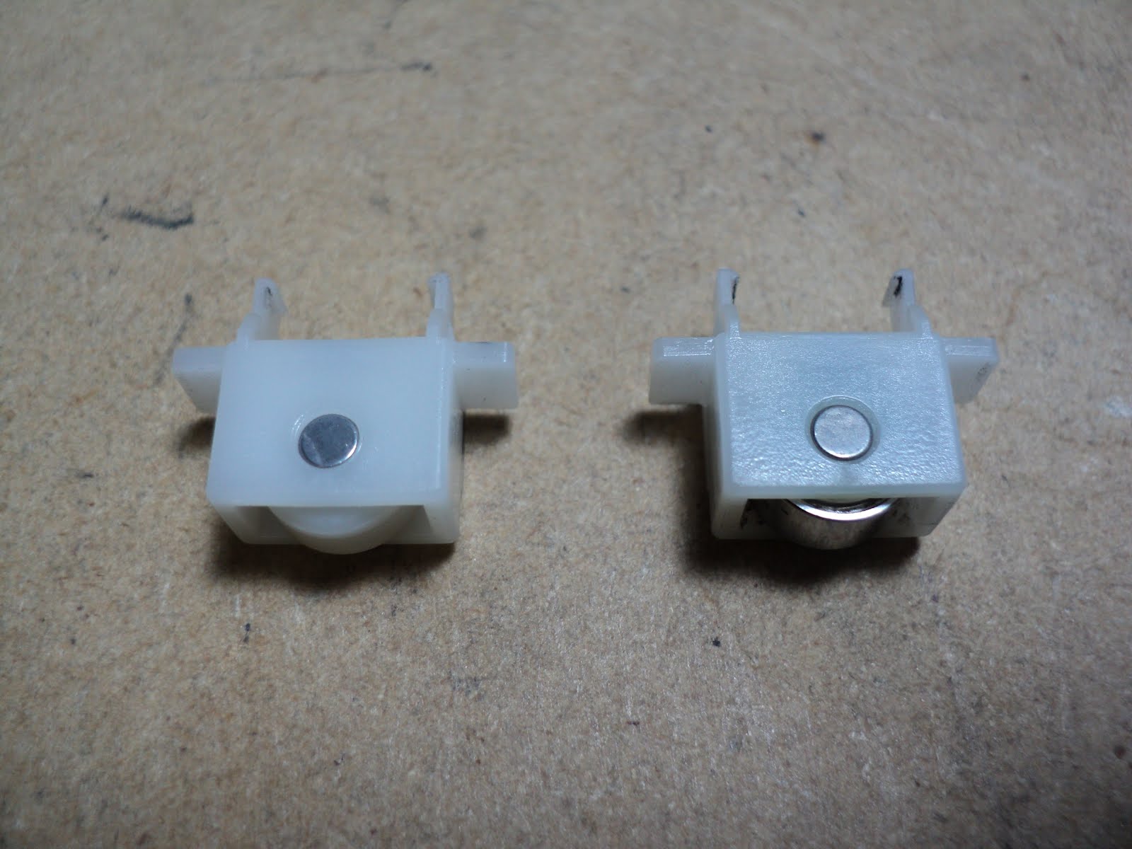 At the left in the above photo is the early, plastic roller. The revised item with a steel ball bearing for a roller is at the right.
The early rollers were prone to flat-spotting. That would lead to poor space motor pinion engagement with the space rack. The pinion would jump teeth on the space rack. The user would see it as margin drift, with the occasional space alarm fatal error when the carriage would crash a stop.
The new roller is P/N 40917101.
Paper Path Change Lever
The early change lever was prone to let the change gear slip out of mesh with the rear tractor drive gear. Oki lengthened the change gear displacement surface on the change lever to solve that. Pictured below are the two versions of change lever.
 [I've blackened the changed portion to make it more discernable.]
At the left is the original lever. At the right is the modified lever with its extra change gear displacement surface. You need only remove a printer's cover to be able to see the affected portion of a lever to check whether the new-style part has been installed. The part number for a new-style lever is 50809501.
The lever is force-fitted onto a splined shaft.To remove one, proceed as follows:
1) Remove platen.
2) Remove the gear train's reset leaf spring and all three gears.
3) Set the change lever to its centre (friction feed) position.
4) Apply one screwdriver as a fulcrum, and a big-enough plain slot screwdriver as a lever in this manner.
 You'll be able to pry the part loose with no risk of breaking anything, although there's a claw on the lever at the inner wall of the chassis that may break off if you don't deflect it forward.
To install a new lever, get the lever in position at the end of the splined shaft with the flats lined up. Then, use a pair of Channellock pliers to press the new part onto the shaft, like so.
 I should be using slightly larger Channellocks. The ones in the photo are just barely adequate.
- - -
Rear Feed Paper-Out Sensor Toggle
The change to this part is subtle, but it does seem to make cut-sheet sensing more reliable. Here's a view of the old and new parts.
 The old part is at the left, the new part is at the right. Note the different profiles. The part number for the new part is 50809301.
Remove the platen and the platen cradle to gain access to the part. Pry gently to pop the part out of its pivot points.
- - -
Rear Feed Paper-Out Sensor Flag
This will always be a weak point, no matter what's done to it.
The part is deflected by paper presence. When the paper is gone, the part is supposed to return to its at-rest position by force of gravity. The part's 'axle' gets fouled with paper dust eventually, and hangs up in its deflected position. The printer is then always sensing a paper-in condition. If you try to park continuous forms, the forms will unload entirely -- the printer can't tell when the forms' leading edge has left the sensor.
To get at the part, remove the platen, platen cradle and the logic PCA at the left side. Here's a view of three versions of the part.
 At the top is the original part. Below it is Oki's improved version. Note the relieved axle -- it's less prone to fouling with paper dust, but it still fouls eventually. The part number for the new version is 40775901.
A further change that Oki made was to add a cover over the axle's pivot cradle. That's pretty much useless; I just take them off and discard them when overhauling a printer.
At the bottom is the part with our modification made to it. We add an M3x6mm pan head screw to the head of the part to give it more weight and make it more responsive to gravity. It's an improvement, but paper dust fouling remains inevitable.
To install the modification, you'll need a drill press and a 7/64" drill. Spot the hole location with an awl. Set up the drill press' depth stop for a drilling depth of 1/4" and drill the hole for the screw.[1]
A 7/64" diameter hole is an interference fit for an M3 screw. Drive the screw all the way in; it will end up securely in place.
- - -
Note
[1] This is doable directly on the drill press' table, there's no need for a drill press vise, but it will seem a bit awkward until you get accustomed to it.
The plastic material exhibits variations in density that allow the drill to seek the path of least resistance at times, resulting in an imperfect but not ruined outcome.
# # #
# # #
No comments:
Post a Comment