Thursday, December 1, 2011

Lexmark E260d -- Cover Removal

Proceed as follows:

1) Cartridge

2) Tray 1

3) Left Side Cover
- One M3x6mm bright washerhead screw at front by Tray 1 cavity.
- One M3x6mm bright washerhead screw at rear underside.
- Two claws at underside.
- Tip out the bottom and lift to remove.

4) Right Side Cover
- One M3x6mm bright washerhead screw at front by Tray 1 cavity.
- One M3x6mm bright washerhead screw at centre underside.
- One claw at rear underside.
- One claw at front just above the screw location.
- Tip out the bottom and lift to remove.

5) Back Door
- Open door and tug forcefully to pop it off its hinge pins.

6) Back Cover
- Two M4x8mm bright washerhead threading screws.
- One claw high up at either side.
- Tip away the top and lift the cover off two hook points at the bottom.

7) Top Cover
- Four M3x6mm bright washerhead screws, two at either side.
- Lift the cover off.

# # #


# # #

Monday, November 28, 2011

Lexmark T63X/64X -- Autocompensator Ball Clutch & Axle

Occasionally, you'll encounter a ball-clutch/axle assembly where the parts of it won't stay put as they should; they tend to wander off axially. The main, outboard portion of the clutch tends to move rightward, as does the axle.

To secure the clutch's hub to the axle, you can apply CA adhesive and let it wick in between the clutch's hub and the axle, but there's a risk of overdoing the glue application and fouling the clutch. A safer, more elegant way to do it is to install a tiny threading screw through the hub and into the axle. Here's a view of that done.

The screw is an M2x6mm one that I got from a T640's fuser exit sensor. A 1/16" diameter hole accepts the screw perfectly. Spot the hole's location with an awl; drill the hole with a pickup roller in place so as to be certain of ending up with the hub properly positioned axially. That hub will never wander again.

To restrain the axle from shifting rightward, apply a small (three-inch) ty-wrap around the axle as a 'retaining ring' just to the left of the beam's hub. Here's a view of that.

Install the ty-wrap as tightly as you can possibly get it.

With those two modifications made, the ball-clutch/axle assembly will retain its axial position and behave itself.

# # #


# # #

Friday, November 25, 2011

Oki 320/1 Turbo -- Early Engineering Changes

Revision 'A' and early revision 'B' machines had changes made to four parts -- the space rack backup roller, the paper path change lever, the rear feed paper-out sensor toggle and the rear feed paper-out sensor flag. Following is an explanation of the changes, and a further improvement to the paper-out sensor flag that we came up with here at West Hill Printers.

- - -

Space Rack Backup Roller

At the left in the above photo is the early, plastic roller. The revised item with a steel ball bearing for a roller is at the right.

The early rollers were prone to flat-spotting. That would lead to poor space motor pinion engagement with the space rack. The pinion would jump teeth on the space rack. The user would see it as margin drift, with the occasional space alarm fatal error when the carriage would crash a stop.

The new roller is P/N 40917101.

Paper Path Change Lever

The early change lever was prone to let the change gear slip out of mesh with the rear tractor drive gear. Oki lengthened the change gear displacement surface on the change lever to solve that. Pictured below are the two versions of change lever.

[I've blackened the changed portion to make it more discernable.]

At the left is the original lever. At the right is the modified lever with its extra change gear displacement surface. You need only remove a printer's cover to be able to see the affected portion of a lever to check whether the new-style part has been installed. The part number for a new-style lever is 50809501.

The lever is force-fitted onto a splined shaft.To remove one, proceed as follows:

1) Remove platen.

2) Remove the gear train's reset leaf spring and all three gears.

3) Set the change lever to its centre (friction feed) position.

4) Apply one screwdriver as a fulcrum, and a big-enough plain slot screwdriver as a lever in this manner.

You'll be able to pry the part loose with no risk of breaking anything, although there's a claw on the lever at the inner wall of the chassis that may break off if you don't deflect it forward.

To install a new lever, get the lever in position at the end of the splined shaft with the flats lined up. Then, use a pair of Channellock pliers to press the new part onto the shaft, like so.

I should be using slightly larger Channellocks. The ones in the photo are just barely adequate.

- - -

Rear Feed Paper-Out Sensor Toggle

The change to this part is subtle, but it does seem to make cut-sheet sensing more reliable. Here's a view of the old and new parts.

The old part is at the left, the new part is at the right. Note the different profiles. The part number for the new part is 50809301.

Remove the platen and the platen cradle to gain access to the part. Pry gently to pop the part out of its pivot points.

- - -

Rear Feed Paper-Out Sensor Flag

This will always be a weak point, no matter what's done to it.

The part is deflected by paper presence. When the paper is gone, the part is supposed to return to its at-rest position by force of gravity. The part's 'axle' gets fouled with paper dust eventually, and hangs up in its deflected position. The printer is then always sensing a paper-in condition. If you try to park continuous forms, the forms will unload entirely -- the printer can't tell when the forms' leading edge has left the sensor.

To get at the part, remove the platen, platen cradle and the logic PCA at the left side. Here's a view of three versions of the part.

At the top is the original part. Below it is Oki's improved version. Note the relieved axle -- it's less prone to fouling with paper dust, but it still fouls eventually. The part number for the new version is 40775901.

A further change that Oki made was to add a cover over the axle's pivot cradle. That's pretty much useless; I just take them off and discard them when overhauling a printer.

At the bottom is the part with our modification made to it. We add an M3x6mm pan head screw to the head of the part to give it more weight and make it more responsive to gravity. It's an improvement, but paper dust fouling remains inevitable.

To install the modification, you'll need a drill press and a 7/64" drill. Spot the hole location with an awl. Set up the drill press' depth stop for a drilling depth of 1/4" and drill the hole for the screw.[1]

A 7/64" diameter hole is an interference fit for an M3 screw. Drive the screw all the way in; it will end up securely in place.

- - -

Note

[1] This is doable directly on the drill press' table, there's no need for a drill press vise, but it will seem a bit awkward until you get accustomed to it.

The plastic material exhibits variations in density that allow the drill to seek the path of least resistance at times, resulting in an imperfect but not ruined outcome.

# # #


# # #

Thursday, November 24, 2011

HP LaserJet 42X0/43X0 -- Delivery Assembly & Duplexing Pendulum Assembly Removal

The gearing in these two units tends to get fouled with debris when a swing plate has worn badly. The assemblies are easily removed for a proper gear cleaning.

All that's holding the delivery assembly in place is a single swing-latch bearing at its right side. Here's a view of it.

And here's the bearing unlatched and on its way out.

With that bearing removed, the right side of the delivery assembly can be lifted, and the assembly can be shifted rightward to free it from the left side vertical frame member. (There's a small sensor cable at the right side that has to be freed from a slot.)

The duplexing pendulum is fastened by two M3x8mm washerhead screws. It comes out easily, but it's one of those parts that can be disorienting when you go to reinstall it. Here's a view of it in the machine with the delivery assembly removed.


There's no need to grease any of the gears, just apply WD-40 to their spindles.

# # #


# # #

HP LaserJet 42X0/43X0 -- Swing Plate Replacement

Swing plate replacement is not a difficult job. We strongly advise against the short-cut method of replacing only the rearmost black gear. That's not a legitimate short-cut; it's a job half done that will soon fail.

A machine with badly worn swing plate gears will have a lot of gear tooth fallout fouling other gears. If at all possible, such machines should be repaired in a shop equipped with compressed air and a parts washer tank.

Proceed as follows:

1) Cartridge

2) Tray 2

3) Back Door
- Pry right side hinge inward to free hinge pin.

4) Top Rear Cover
- Pull it straight up.

5) Right Side Rear Cover (Formatter Cover)
- Pull it straight back.

6) Duplexer Slot Insert (if present)
- Pull it straight back.

7) Tray 2 Rear Concealment Cover
- Tip it up and pry loose its left side hinge pin.

8) Fuser

9) Cartridge Engagement Arm
- Disconnect it from the cartridge access door and lower it.
- NOTE: The arm must be fully lowered for swing plate assembly
removal and replacement.

10) Top Cover Assembly
- Four M3x8mm washerhead screws.
- Lift cover up an inch.
- Disconnect control panel cable -- right side near the middle.
- Lift the cover away completely.


11) Formatter Cage
- Two M3x6mm bright washerhead screws at the rear.
- Pull the item straight rearward to unplug/remove it.

12) Right Side Cover
- One large claw at upper rear.
- One tab at arrowhead in front behind tray 1 door.
- One claw at arrowhead in front just below tray 1 door.
- NOTE: MIND the switch rod/rocker connection when reinstalling this cover.

13) Left Side Cover
- One claw at top centre.
- One claw at arrowhead in front behind tray 1 door.

14) Fan Connector Cover P/N RC1-0344 (Sheet metal rectangle below fan on left side.)
- Two M3x8mm washerhead screws at locations ‘M3’.

15) Fan and Thermistor Cable Connections
- NOTE: Make certain that the cable ends are outside the chassis where they can't get snagged when removing and reinstalling the power supply.

16) Right Side Duplexer Way
- Two M4x10mm bright pan head threading screws.
- One latch button at arrowhead; slide the item rearward to
remove it.

17) Switch Rod
- NOTE that the long, straight arm goes outboard.

18) Two Flat Cables

19) Three Red Cables (Does not apply to 4300.)

20) DC Power Cable

21) Pull the cables into the tray 2 cavity

22) Power Supply
- One M3x6mm bright pan head screw w/captive washer at right
side.
- Three M3x8mm washerhead screws at right side.
- Three M3x8mm washerhead screws at left side.
- MIND THE CABLING AS YOU PROCEED.
- Lift the back end of the unit slightly and it can be slid
out the rear. Take care not to damage the two flat cables.

23) Power Supply Right Side Way
- One M3x8mm washerhead screw just above the formatter
connector.
- One latch button; slide the item rearward to remove it.
- Replace the screw with a 4mm long washerhead screw, and the screw will no longer interfere with removal/replacement of this item.

24) Rectangular Grommet below swing plate assembly
- Two claws. Push the grommet inward so it’s clear of the
swing plate assembly.

25) Swing Plate Assembly
- WARNING: Use only a high quality No. 2 Phillips screwdriver
in perfect condition for this. The screws are usually very
tight, and must not have their recesses reamed by cam-out.
The awkward placement of the screws would make a reamed
screw recess very difficult to deal with.
- NOTE: The swing plate comes away quite easily, but it can be remarkably difficult to get one into place. Try to observe the path it takes as you remove it to gain familiarity with its fit. Remember that the cartridge engagement arm must be fully lowered for the swing plate to go in.
- Three M3x6mm black washerhead screws.

- - -

Gear Cleaning

As mentioned earlier, several gears are likely to be fouled with debris from worn swing plate gears.

The large gear that drives the swing plate can't be removed easily; it must be cleaned in situ. It should be lightly greased once cleaned.

The large gear next to that gear has a claw-latch; it can be removed easily for cleaning. There's no need for grease to be applied to it -- it's very lightly loaded; all it drives is the little 'conveyor-belts' affair at the upper front of the power supply assembly.

If the fuser is good to reuse, its gears will likely need cleaning.

The gearing associated with the delivery assembly is not difficult to take out for cleaning. See this post for some help with that.

- - -

SWING PLATE REINSTALLATION NOTES

a) There are two small white plastic glide-buttons plugged into rectangular holes in the swing arm. Check that they are both present and properly seated.

b) Check that the swing arm retraction spring is in place, that the swing arm pivots freely, and that the spring pulls the swing arm back to its stop smartly and fully.

c) Swing plate reinsertion is accomplished by tipping the upper portion of the assembly up in behind two plastic parts. Here's a view of the part's attitude as it's just about to go into place easily.


d) It’s a good practice to replace the three washerhead screws with hex head screws. It will be easier to tighten the screws with a nutdriver, and any subsequent swing plate assembly replacement will be easier.

e) When properly installed, raising the cartridge release arm should cause the fuser drive gear to lift. Lowering the cartridge release arm should permit the fuser drive gear to drop. THE FUSER DRIVE GEAR MUST DROP FREELY AND SMARTLY TO ITS ENGAGEMENT POSITION. IT MUST NOT BIND.

# # #


# # #

Wednesday, November 23, 2011

HP LaserJet 4100 -- "Perform Printer Maintenance" Message

Maintenance Interval

Maintenance interval is 200,000 pages.

Clearing the Message

To clear the message, press and hold '-Item' and -'Value' while powering on the printer. Release the keys when you see " RESET MAINT COUNT" in the display. The MAINTENANCE COUNT item in the Service Menu gets reset to zero.

Clearing the Message Temporarily

This is a user convenience feature that permits one to put off seeing the message for another 10,000 pages. In the Configuration Menu there'll be an item, MAINTENANCE MESSAGE = OFF. Select it, and the message will go away for awhile.

# # #


# # #

HP LaserJet 4100 -- Routine Teardown/Overhaul

The 4100 has two weak points that routinely cause paper jams, and should be attended to when performing a routine overhaul:

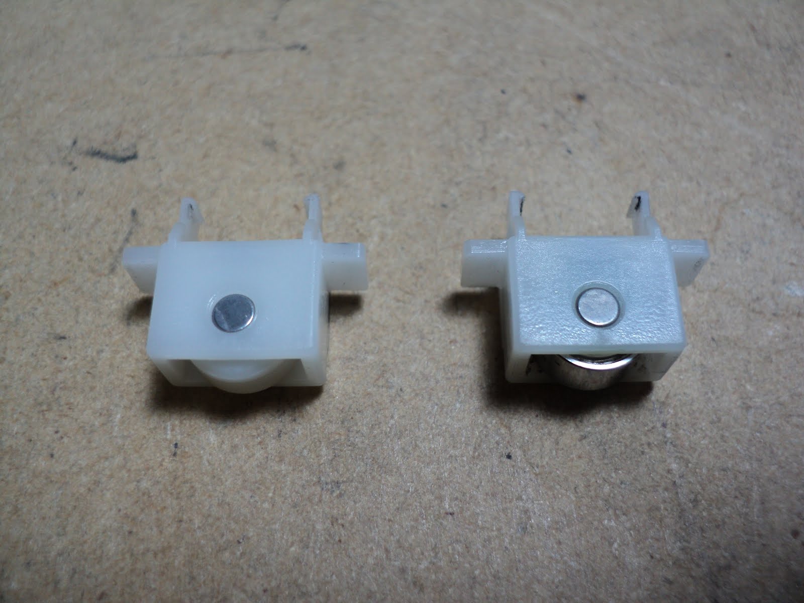
a) The pickup solenoids become sticky with age. See this post for more information, and a repair method

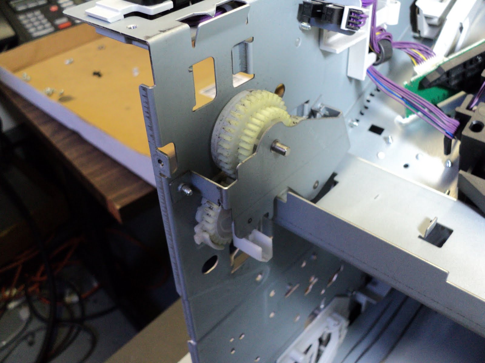
b) A roller clutch on the paper feed assembly is prone to gum up and slip. See this post for service information.

- - -

Proceed as follows:

1) Cartridge

2) Tray 2

3) Tray 2 Rear End Cover (if present)
- Two claws high up, accessible through small rectangular openings.

4) Back Door
- Open it and pry at the right side hinge to free the door.

5) Fuser
- Two lock levers.

6) Rear Right Side Cover (Formatter Cover)
- Tug it rearward to remove it.

7) Control Panel Overlay
- Pry at its right side lip to free two small claws.

8) Control Panel
- There's a claw at either side near the front. Nudge them with a small screwdriver to free them.
- One cable connection.

9) Top Cover
- Two M4x12mm bright pan head threading screws at the back.
- Two M4x12mm bright pan head threading screws under the toner cartridge access door.
- Cartridge engagement arm -- free its upper end.
- Pry at the right front to free the right front corner.
- Tug the front of the cover up forcefully to free it.
- NOTE: The door's hinges are easily separated to facilitate washing the door and cover.

10) Front Right side Cover
- One claw at the top.
- NOTE: MIND the switch rocker/rod engagement when reinstalling this cover.

11) Left Side Cover
- Lift it slightly and tip it away.

12) Tray 1 Door
- Pry gently to free the inner platform from its ways.
- Slide the door rightward off its hinges.

13) Tray 1 Platform w/Sensor Arm Cover and Torsion Spring
- Disengage the torsion spring.
- Tug forcefully on the sensor arm cover to pop it off the pickup shaft.
- Lower the platform a bit and it can be slipped off its left side hinge pin.

14) Two Extended Head M4 Screws near the Front
- The left side screw is visible by the yellow cable for Tray 1's paper-out sensor.
- The right side screw's head is just below and to the right of the envelope feeder connector.

15) Tray 1 Pickup Assembly w/Left Side Cartridge Guide
- One in-line cable connection for the pickup solenoid.
- One cable connection for the paper-out sensor.
- Five M4x12mm bright pan head threading screws in front. Three of them are in deep wells.
- INSPECT the pickup solenoid for stickiness.

16) Paper Feed Assembly
- One in-line cable connection.
- Two M4x12mm bright pan head threading screws. NOTE that these are in the upper holes of the brackets. The two lower holes are where two of the Tray 1 pickup assembly's screws go.

17) Cover-Open Switch Bracket
- One M3x6mm bright pan head screw w/captive star washer at blue ground wire terminal.
- One M4x12mm bright pan head threading screw forward of and below the previous screw.
- Free the bracket and let it dangle by the side of the machine.

18) Registration Assembly
- One M3x6mm bright pan head screw w/captive star washer at the extreme right.
- NOTE. There is an M3 hex head screw forward of and to the left of the previous screw. DO NOT loosen it.
- Five M4x12mm bright pan head threading screws.
- Overhaul per this post.

19) Pre-Transfer Ground Plate
- Tip up its right side end and slip it out.

20) Delivery Assembly
- The left side white bearing unhooks easily and lifts out.
- The right side bronze bearing has a lever on it. Swing the lever up to vertical and the unit can be lifted out.
- Overhaul per this post. (Scroll down to "To dismantle...".)

21) Printhead
- Three cable connections.
- One M3x8mm pan head threading screw at blue ground wire terminal.
- Four M4x12mm bright pan head threading screws.
- DO NOT DISTURB the hex recess head screw at the centre rear. It was factory-adjusted for optical skew correction.

22) Formatter Cage
- One M3x6mm bright washerhead screw at an upper, forward-pointing tab.
- One M4x10mm black pan head threading screw at a lower, forward-pointing tab.
- Tug the cage rearward to disconnect it.

23) Right Side Engine-to-Tray Module Attachment
- Two M3x6mm bright pan head screws w/captive star washers.

24) Fourteen-Conductor Cable Connector
- Unplug it and free it from its hooks.

25) One M4x12mm Bright Pan Head Threading Screw
- It's at the left side, just below and behind the lower rear corner of the fan.

26) Engine Chassis
- It's free to be lifted off the paper tray module.
- Blow out the chassis w/compressed air.

27) Engine Controller PCA
- NOTE: This part needn't be removed, but it should be unfastened so the PCA and its environs can be blown out with compressed air.
- Switch rod. Disengage its rear end from the switch and move the rod aside.
- Three cable connections at the fan side of the PCA.
- Four M4x12mm bright pan head threading screws.
- Three M3x6mm bright pan head screws w/captive washers.

28) Tray 2 Top Cover
- Two M3x6mm black pan head screws.
- Four M4x10mm black pan head threading screws.

29) Tray 2 Pickup Assembly
- One two-conductor cable connection. Free the black cable from its restraints.
- Lift the unit out.
- Clean/replace rollers A/R.
- INSPECT the pickup solenoid for stickiness.

30) PCA Cover
- Two claws at the top edge.

31) PCA P/N RG5-2673
- Two cable connections.
- Two claws.
- Apply WD-40 to the pushbutton switches and actuate them many times. Blow them out w/compressed air.

32) Blow out and clean the base A/R.

33) Reassemble the tray module.


34) Reinstall the chassis on the tray module.

35) Reassemble from step '25)'.

# # #


# # #